EasyManua.ls Logo

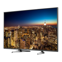
Panasonic TX-55DX650B User Manual

Panasonic TX-55DX650B
85 pages
To Next Page IconTo Next Page
Page #1 background imageLoading...
Page #1 background image
Service Manual
LED TV
TX-55DX650B
LA64 Chassis
© Panasonic Corporation 2016.
Unauthorized copying
and
distribution is a violation of law.
ORDER No. PCZ1604118CE
There are special components used in this equipment which are important for safety. These parts are marked in the
Schematic Diagrams, Circuit Board Diagrams, Explorer Views and Replacement Parts List. It is essential that these
critical parts should be replaced with manufacturer´s specified parts to prevent shock, fire or other hazards. Do not
modify the original design without permission of manufacturer.
IMPORTANT SAFETY NOTICE
This service information is designed for experienced repair technicians only and is not designed for use by the general public. It does not
contain warnings or cautions to advise non-technical individuals of potencial dangers in attempting to service a product. Products
powered by electricity should be serviced or repaired only by experienced professional technicians. Any attempt to service or repair the
product or products deal within this service information by anyone else could result in serious injury or death.
Warning
Question and Answer IconNeed help?

Do you have a question about the Panasonic TX-55DX650B and is the answer not in the manual?

Panasonic TX-55DX650B Specifications

General IconGeneral
Screen Size55 inches
Display TechnologyLED
HDRYes
Smart TVYes
Operating SystemFirefox OS
HDMI Ports3
USB Ports3
Built-in Wi-FiYes
BluetoothNo
Resolution3840 x 2160
Audio Output20W

Summary

Safety Precautions

General Guide Lines

General guidelines for servicing, covering lead dress, protective devices, and cover labels.

Touch-Current Check

Procedures for checking touch current to prevent shock hazards using a measuring network.

Prevention of Electrostatic Discharge (ESD)

Lead Free Solder (PbF) Information

Suggested Pb Free Solder

Lists recommended types of lead-free solder for repairs and their specifications.

Service Navigation

Chassis Board Layout

Identifies and describes the main circuit boards (A-Board, P-Board, K-Board) within the chassis.

Service Hints

Pedestal Assembly Removal

Step-by-step instructions and diagrams for removing the TV's pedestal assembly.

Back Cover Removal

Instructions for removing the back cover, detailing screw locations and types.

Service Hints: LCD Panel Replacement

LCD Panel Replacement Preparation

Detailed steps for preparing to replace the LCD panel, including bezel removal.

Service Hints: LCD Panel Assembly

LCD Panel and Cabinet Assembly

Instructions for assembling the LCD panel with the cabinet, including screw details.

Applicable Signals

Specifications

Specifications: Dimensions & Audio

Audio Output and Headphones

Details the audio output power, headphone impedance, and related accessories.

Dimensions and Mass

Provides physical dimensions and weight of the TV, with and without the stand.

Technical Description

Key Specifications for Content Protection

Details key specifications and requirements for various content protection and streaming services.

IC Replacement and KEY Generation

Procedures for replacing MTK IC (IC8000) and eMMc (IC8920) and generating KEY data.

Model-Specific Key Support

Table mapping model numbers to supported keys for various features like DTCP-IP, HDCP, etc.

USB HDD Recording Details

Information on recording digital TV programs to USB HDD and the role of C2MOD key.

Setting Inspection

Voltage Confirmation Points

Lists test points and expected voltages for the A-board and P-board for verification.

CS Maintenance Menu

Accessing CS Maintenance Menu

Steps to access the CS Maintenance Menu using specific button sequences on the remote.

Exiting CS Maintenance Menu

Instructions on how to exit the CS Maintenance Menu.

OPT Settings in CS Menu

How to select and adjust OPT settings within the CS Maintenance Menu using remote control.

CS Maintenance Menu Operations

EDID Clock Adjustment

Procedure to adjust EDID Clock settings within the CS Maintenance Menu via remote.

USB HDD Drive Check

Steps to perform a drive check for USB HDD within the CS Maintenance Menu.

White Balance Adjustment (WB-ADJ)

Procedure for White Balance adjustment within the CS Maintenance Menu, covering gain and color temp.

System Information Access

Accessing System Information Display

Instructions on how to access the System Information menu from the main menu.

Exiting System Information Display

Instructions on how to exit the System Information display.

Hotel Mode Configuration

Hotel Mode Purpose and Access

Explains the purpose of Hotel Mode and the specific button sequence for menu access.

Exiting Hotel Mode Settings

Instructions on how to exit the Hotel mode.

Hotel Mode Menu Options

Explains the various settings and options available within the Hotel mode setup menu.

USB Data Copy Procedures

Purpose of USB Data Copy

Explains the purpose of data copy via USB for board replacement or hotel installations.

USB Data Copy Preparation Steps

Steps to prepare a USB memory stick by creating a startup file (pwd file) for data copying.

TV to USB Memory Data Transfer

USB Memory to TV Data Transfer

Option Bytes Description

Self Check Functionality

Accessing Self Check Modes

Instructions on how to access self-check indications and force factory settings.

Exiting Self Check Mode

Instructions on how to exit the self-check mode.

Power LED Blinking Fault Codes

LCD Panel Test Mode Operations

LCD Panel Test Mode Purpose

Explains the purpose of the LCD Panel Test Mode for diagnosing picture issues.

Entering LCD Panel Test Mode

Steps to enter the LCD Panel Test Mode using remote control commands.

Exiting LCD Panel Test Mode

Instructions on how to exit the LCD Panel Test Mode.

Picture Issue Diagnosis Confirmation

Method for confirming the cause of abnormal picture after running test patterns.

LCD Panel Test Mode Remarks

Notes on how test patterns are created and their implications for diagnosis.

Wiring Diagram Overview

Block Diagram (Part 1)

Block Diagram (Part 2)

Parts Location Guide

Parts Location Details (Chassis)

Parts Location Details (Cabinet)

Lead Wiring Location Guide

Heat Rubbers and Gaskets Location

Packing Structure Diagram

Replacement Parts List Notes

Retention Time Limited (RTL) Items

Explains items marked RTL, indicating limited availability after production discontinuation.

Part Name and Description Abbreviations

Explains abbreviations used for resistors and capacitors, including type and allowance codes.

Parts List: TX-55DX650B

Schematic Diagrams Notes

A-BOARD Schematic Diagrams

P-BOARD Schematic Diagrams

K-BOARD Schematic

Conductor Views: A-BOARD Top

A-BOARD Bottom View

P-BOARD Top View

P-BOARD Bottom View

K-BOARD Views

Related product manuals