1
1-271
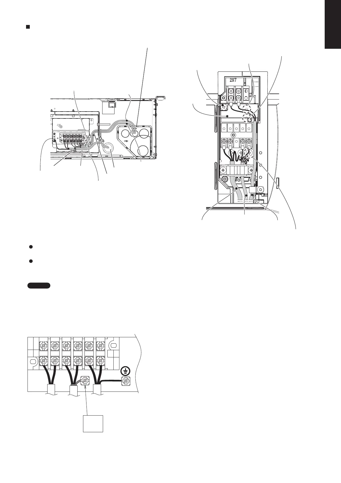
Wiring samples
Type K1
L1
R1 R2
L2 N U1 U2
Functional ground screw (External Electronic
Expansion Valve Kit and Schedule Timer)*
Protective ground screw
Use this screw when connecting the shield
for the Inter-unit control wiring to ground.
* As to functional ground screw and protective ground screw,
remove the fixture screw and resin cover. Then, carry out
earth ground work.
Power Supply
Fixture screw for resin cover
Resin cover
Inter-unit Control Wiring
Remote Control Wiring
Type N1
6P terminal board
R1
R2
U1
U2
L
N
Remote
controller
line
Unit
control
wiring
Power
suppy
Earth
Shielded
wire
ground
How to carry out power supply wiring
(1)
The power inlet port is located at the rear.
The remote control wiring inlet port is located at the rear
(for use with the wired remote controller).
Be sure to use sealing putty to seal off the opening
to prevent dust.
(2)
Wiring connection ports
How to carry out wiring
Insert the power wiring into the indoor unit through the rubber
at the side of the electrical component box.
For wiring connection to the outdoor unit and remote control
wiring, open the elongated hole of the piping cover and pass
the wires through the hole.
NOTE
Type T2
Protective ground screw
Functional ground screw (Schedule Timer)
Power wiring
Remote control wiring and inter-unit control wiring inlet port
* Insert the remote control wiring and inter-
unit control wiring into the electrical
component box from the inlet port as
shown in the figure. This is done regardless
of whether the wiring was inserted from the
top, rear, or left side of the main unit.
Clamp
Inter-unit Control Wiring
Power inlet port
Clamp
Use this screw when connecting the shield
for the Inter-unit control wiring to ground.
Remote Control Wiring
SM830231-02Single欧州.indb271SM830231-02Single欧州.indb271 2014/09/1913:21:442014/09/1913:21:44
 Loading...