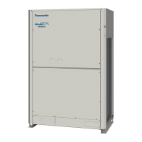
Do you have a question about the Panasonic U-12ME2E8 and is the answer not in the manual?
Electric shock hazard during wiring. Qualified electrician required.
Insulate tubing to prevent sweating and water damage.
Use a level foundation for outdoor unit to prevent water damage.
Securely anchor outdoor unit with bolts and metal frame.
Install outdoor unit on a raised platform higher than snow.
Hazards of mixing air with refrigerant, toxic gas from flame contact.
Do not modify or disassemble. User cleaning prohibited. Contact dealer for repairs.
Ventilate enclosed areas. Confirm no refrigerant leaks after installation.
Avoid touching sharp fins, do not sit on unit, keep objects out of fan case.
Use seamless copper tube, follow wall thickness, avoid bending hard copper tube.
Tool specifications differ for R410A; R22/R407C tools may not be compatible.
Overview of ME2 series outdoor units and system configuration.
Rules for main/sub unit selection, delayed start, and stop logic.
Details on compressors, selection rules, operating frequency, and protection.
Functions like 4-way valve, SAVE valve, oil recovery, and others.
Fan motor control, modes, silent, and high static pressure settings.
Control of indoor units via CCU, including MOV and drain pump.
Oil level detection, recovery, and system oil recovery control.
Detects room temp via sensors and controls thermostat based on delta T.
Automatically selects heating/cooling mode based on temp differences.
Controls discharge air temp using indoor unit sensor for dew prevention.
Default settings for indoor units like correction temp and heat/cool switching.
Procedures for safely removing front panels and covers.
Steps for draining and checking compressor oil condition.
Procedures for safely recovering refrigerant before servicing.
Steps to remove refrigerant and nitrogen from the repaired unit.
Troubleshooting, diagnosis, and replacement procedures for compressors.
Introduction to the CZ-RTC4 maintenance remote controller and its purpose.
Description of controller functions, display options, and mode settings.
Details on using the remote controller for basic operations and display.
How to display indoor and outdoor unit sensor temperatures.
How to check recorded outdoor unit alarms and history.
Procedures for changing various operational modes and settings.
Allows setting filter lifetime, operating mode priority, and addresses.
For system, indoor unit, and group control settings.
Accessing test runs, sensor info, simple/detailed settings, and auto address.
Lists causes of malfunctions and related indicators.
Explains meanings of LED indicators for system status and auto address.
Comprehensive list of alarm codes, meanings, and troubleshooting steps.
Information on automatic backup mode display.
Details on checking components like switches, valves, and heaters.
Troubleshooting guide for thermostat cycling issues.
Pre-test checks including power, connections, and component removal.
Step-by-step guide for performing the test run.
Details on configuring DIP switches and rotary switches on the PCB.
Procedures for setting indoor/outdoor unit addresses automatically.
How to use the remote controller for test run configurations.
Procedure for safely returning refrigerant gas to the outdoor unit.
Table of alarms and their meanings for self-diagnosis.
| Cooling Capacity | 3.5 kW |
|---|---|
| Heating Capacity | 4.0 kW |
| Refrigerant | R32 |
| Energy Efficiency Ratio (EER) | 3.21 |
| Coefficient of Performance (COP) | 3.61 |
| Power Supply | 220-240V, 50Hz |
| Type | Split System |
| Outdoor Unit Noise Level | 48 dB(A) |


 Loading...