Do you have a question about the Panasonic WH-MXC09J3E8 and is the answer not in the manual?
Covers essential safety warnings and precautions to prevent injury or property damage.
Specific instructions for handling R32 refrigerant safely and correctly.
Detailed technical specifications for the WH-MXC09J3E8 model.
Detailed technical specifications for the WH-MXC12J9E8 model.
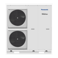
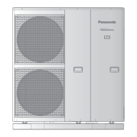
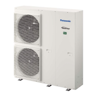
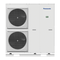
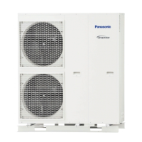
Highlights key features including inverter technology, efficiency, and design.
Details of the indoor unit's remote controller buttons and LCD display functions.
Procedure for initial setup of language, date, time, and quick menu settings.
Explanation of user-accessible menus for system settings and function setup.
Configuration options for installers, including PCB connectivity and system setup.
Detailed dimensions and physical specifications for the Mono Bloc Unit.
Schematic diagram illustrating the refrigeration and water cycles of the Mono Bloc Unit.
Diagrams for standard and advanced system configurations with optional PCB.
Block diagram illustrating the electrical and system components for the WH-MXC09J3E8 model.
Block diagram illustrating the electrical and system components for the WH-MXC12J9E8 model.
Wiring diagram for the water system of the WH-MXC09J3E8 model.
Wiring diagram for the water system of the WH-MXC12J9E8 model.
Wiring diagram for the refrigerant system of the WH-MXC09J3E8 and WH-MXC12J9E8 models.
Electronic circuit diagram for the water system of the WH-MXC09J3E8 model.
Electronic circuit diagram for the water system of the WH-MXC12J9E8 model.
Electronic circuit diagram for the refrigerant system of the WH-MXC09J3E8 and WH-MXC12J9E8 models.
Layout of the main printed circuit board for the water system of the WH-MXC09J3E8 model.
Layout of the optional printed circuit board for the water system.
Layout of the main printed circuit board for the refrigerant system.
Layout of the noise filter printed circuit board.
Instructions for installing the Mono Bloc Unit, including location selection and mounting.
Detailed instructions for water piping installation, including safety and compliance.
Instructions for connecting power supply cables and managing drainage piping.
Requirements for connecting power cables and proper wire stripping techniques.
Instructions for connecting optional external devices like valves and sensors.
Guidance on routing optional cables and power supply cords to the unit's bushing points.
Instructions for wiring and physically mounting the remote controller.
Procedure for installing optional network adaptor and base pan heater.
Steps for filling the system with water and performing essential pressure checks.
Procedures for checking RCCB, performing test runs, and checking water flow.
Step-by-step guide for cleaning and maintaining the magnetic water filter set.
Explains different methods for setting temperatures for heating applications.
Details on using room thermistors and examples of multi-zone installations.
Examples of floor heating, radiator, and swimming pool system configurations.
Examples for swimming pool only and simple 2-zone control systems.
Application configurations for DHW tank and DHW tank with solar water heater.
Application configurations for buffer tank and buffer tank with solar water heater.
Application configuration for connecting a boiler as an auxiliary heat source.
Guidelines for cable connections, PCB interfaces, and recommended external device specifications.
Specifications for recommended external devices like sensors and pumps.
Overview of the remote controller's display, buttons, and their functions.
Step-by-step guide for the initial power-on and setup process of the system.
Detailed breakdown of installer setup options for system configuration.
Configuration settings for various operation modes like Heat, Cool, Tank, and Service.
System setup options related to optional PCB connectivity and tank connection.
System setup for DHW capacity, heaters, and alternative sensors.
System setup options for bivalent connection and external switch control.
System setup for solar connection, external error signals, and demand control.
System setup for external compressor, circulation liquid, and heat/cool switching.
Configuration parameters for heating operation, including water temperatures and heater control.
Settings for automatic mode switching and tank heating operations.
Service setup options for pump speed, dry concrete curing, and contact information.
Procedures for password reset and accessing the maintenance menu for diagnostics.
Custom menu options for setting cool mode, backup heater, and resetting monitors.
Explanation of basic unit functions and detailed control logic for heating operations.
Details on cooling operation and setting target water temperatures for standard systems.
Explanation of compensation type operation, ambient temperature influence, and shift values.
Target water temperature calculation for extension systems with optional PCB.
Control logic for setting target water temperature for Zone 1 and Zone 2, including SG ready.
Details on zone temperature control for standard/extension systems and SG ready logic.
Logic for automatic mode switching between heating and cooling based on conditions.
Limits for auto cooling mode and operation logic for tank heating modes.
Detailed logic for tank operation, including heat pump control and characteristics.
Operational logic for systems combining heat and tank heating modes.
Operational logic for systems combining cooling and tank heating modes.
Description of how the outdoor fan motor operates in relation to the compressor.
Control logic for the water pump and how to adjust its speed settings.
Control logic for zone water pumps, including start/stop conditions and anti-freeze protection.
Explanation of water pump speed feedback errors and troubleshooting steps.
Safety controls for the indoor unit, including flow switch and water inlet temperature monitoring.
How the system restarts automatically after a power interruption.
Explanation of LED indicators on the control panel and their operational meaning.
Control logic for indoor heaters and their operation during deice cycles.
Settings for tank heater selection and temperature control via remote.
Control conditions for external heater operation at the tank side.
Control conditions for internal heater and base pan heater operations.
Logic for prioritizing heater operation and using force heater mode.
Detailed control logic for force heater mode in various scenarios.
How to use powerful operation mode to increase heat capacity and its control details.
How to activate quiet mode to reduce outdoor unit noise and its control logic.
Procedure for setting up and operating the sterilization mode to boil water tank.
Logic to stop heating based on high outdoor ambient temperature for energy saving.
Using an alternative outdoor sensor for improved performance in direct sunlight locations.
How to force DHW mode for immediate tank heating, regardless of other settings.
SMART DHW mode offers lower heat-up power but longer reheat time compared to STANDARD DHW.
Setting the heat pump's heating capacity output for tank boiling operations.
Details on the three types of anti-freeze controls for system protection against freezing.
How to set up and control solar operation for heating DHW or buffer tanks.
Control logic for solar operation and how it functions during errors or specific conditions.
Using a boiler as an alternative heat source, with setup options for control patterns.
Details on different boiler control modes: Alternative, Parallel, and Advance Parallel.
How the 3-way valve controls hot water flow direction between heating and tank sides.
How the 2-way valve controls hot water flow to heating panels or blocks cold water.
How the system operates and displays information when an external switch is connected.
Using the external compressor switch for heat source ON/OFF or heater ON/OFF control for energy management.
Control logic for the heater ON/OFF function via external compressor switch for energy limitation.
How to switch between heating and cooling modes using an external heat/cool switch.
Setting up and operating SG Ready control for heat pump and boiler based on digital input.
Logic for adjusting heating, DHW, and cooling target temperatures based on SG Ready capacity settings.
Using demand control to reduce heat pump unit's current usage via a third-party device.
Setting up and operating the holiday mode for energy saving during periods of absence.
Using the dry concrete function to provide heat for floor panels and dry concrete during installation.
Function of the flow sensor as an overload protector and detection of abnormal flow conditions.
Protection controls including time delay for compressor startup and forced operation.
Protection controls related to total running current and DC peak current to prevent electrical issues.
Protection mechanisms for compressor overheating and high pressure conditions.
Controls for outdoor temperature regulation and crank case heater for compressor protection.
Protection controls for heating operation, including outdoor air temperature regulation and deice operation.
Details on deice modes and how to perform force defrost operations.
Protection controls for cooling operation, including outdoor air temperature and freeze prevention.
Procedures for checking the expansion vessel and maintaining the magnetic water filter.
Step-by-step guide for performing the correct pump down procedure for servicing.
Instructions on how to adjust the pump speed settings via the remote control.
Procedure to unlock the cool mode setting if it is disabled.
Procedure for setting EEPROM to factory default data during initialization.
Steps for setting up the dry concrete function, including stage progression and temperature settings.
Continuing the dry concrete setup by selecting number of stages and temperature for each stage.
Procedures for purging air, checking pressure relief valve, and water pressure.
Procedures for checking RCCB, performing test runs, and confirming water flow rates.
Accessing and using service, maintenance, and custom menus for diagnostics and settings.
Quality limits for tap water used as a heat transfer medium in the brazed heat exchanger.
Diagnosing malfunctions related to the refrigeration cycle, including pressure and current values.
How indoor/outdoor unit conditions affect pressure and electric current in heating and cooling modes.
How to check and interpret error codes displayed by the system's self-diagnosis function.
Procedures for displaying and clearing the system's error history.
Table listing diagnosis codes, abnormalities, judgments, and primary verification locations.
Detailed error codes, their causes, and troubleshooting steps for system issues.
Troubleshooting steps for H12 abnormality related to connection capability rank.
Troubleshooting steps for H15 abnormality related to the compressor tank temperature sensor.
Troubleshooting steps for H20 abnormality related to water pump operation.
Troubleshooting steps for H23 abnormality related to the indoor refrigerant liquid temperature sensor.
Troubleshooting steps for H27 error related to service valve operation.
Troubleshooting steps for H28 abnormality related to the solar sensor.
Troubleshooting steps for H31 abnormality related to the swimming pool sensor.
Troubleshooting steps for H36 abnormality related to the buffer tank sensor.
Troubleshooting steps for H38 abnormality when indoor and outdoor unit brand codes do not match.
Troubleshooting steps for H42 abnormality related to compressor low pressure protection.
Troubleshooting steps for H43 abnormality related to the Zone 1 sensor.
Troubleshooting steps for H44 abnormality related to the Zone 2 sensor.
Troubleshooting steps for H62 abnormality related to the water flow switch.
Troubleshooting steps for H64 abnormality related to outdoor high pressure.
Troubleshooting steps for H65 error related to deice circulation during operation.
Troubleshooting steps for H67 abnormality related to the external thermistor 1.
Troubleshooting steps for H68 abnormality related to the external thermistor 2.
Troubleshooting steps for H70 abnormality related to the indoor backup heater OLP.
Troubleshooting steps for H72 abnormality related to the tank temperature sensor.
Troubleshooting steps for H74 error indicating communication failure between PCBs.
Troubleshooting steps for H76 abnormality related to indoor-control panel communication.
Troubleshooting steps for H90 abnormality indicating communication issues between indoor and outdoor units.
Troubleshooting steps for H91 abnormality related to the tank booster heater OLP.
Troubleshooting steps for H95 abnormality related to unspecified voltage between indoor and outdoor units.
Troubleshooting steps for H98/F95 abnormalities related to outdoor high pressure protection.
Troubleshooting steps for cooling mode abnormalities related to outdoor high pressure.
Troubleshooting steps for H99 abnormality related to indoor freeze-up protection.
Troubleshooting steps for F12 abnormality when the outdoor high pressure switch activates.
Troubleshooting steps for F14 abnormality related to compressor rotation failure.
Troubleshooting steps for F15 abnormality related to the outdoor fan motor mechanism.
Troubleshooting steps for F16 abnormality related to input over current detection.
Troubleshooting steps for F20 abnormality related to compressor overheating.
Troubleshooting steps for F22 abnormality related to IPM overheating.
Troubleshooting steps for F23 abnormality related to output over current detection.
Troubleshooting steps for F24 abnormality related to the refrigeration cycle.
Troubleshooting steps for F25 abnormality related to the four-way valve.
Troubleshooting steps for F27 abnormality when the outdoor high pressure switch is open.
Troubleshooting steps for F30 abnormality related to the indoor water outlet temperature sensor 2.
Troubleshooting steps for F36 abnormality related to the outdoor air temperature sensor.
Troubleshooting steps for F37 abnormality related to the indoor water inlet temperature sensor.
Troubleshooting steps for F40 abnormality related to the outdoor discharge pipe temperature sensor.
Troubleshooting steps for F41 abnormality related to the Power Factor Correction circuitry.
Troubleshooting steps for F42 abnormality related to the outdoor pipe temperature sensor.
Troubleshooting steps for F43 abnormality related to the outdoor defrost temperature sensor.
Troubleshooting steps for F45 abnormality related to the indoor water outlet temperature sensor.
Troubleshooting steps for F46 abnormality related to the outdoor current transformer.
Instructions for safely removing the cabinet front and top plates for access.
Instructions for removing the cabinet rear plate and pressure gauge.
Steps for removing the water system electronic controller board.
Instructions for removing the air purge valve and flow sensor from the unit.
Instructions for disconnecting and removing the water pump.
Steps for removing the heater assembly, including lead wires and bracket.
Procedure for removing the water filter set from the unit.
Heating performance characteristics of the WH-MXC09J3E8 model at different outdoor temperatures.
Cooling performance characteristics of the WH-MXC09J3E8 model at different outdoor temperatures.
Cooling performance characteristics of the WH-MXC12J9E8 model at different outdoor temperatures (Part 1).
Cooling performance characteristics of the WH-MXC12J9E8 model at different outdoor temperatures (Part 2).
Heating performance characteristics of the WH-MXC12J9E8 model at different outdoor temperatures.
Cooling performance characteristics of the WH-MXC12J9E8 model at different outdoor temperatures (Part 1).
Cooling performance characteristics of the WH-MXC12J9E8 model at different outdoor temperatures (Part 2).
Table detailing heating capacity, input power, and current for WH-MXC09J3E8 at various conditions.
Table detailing heating capacity, input power, and current for WH-MXC12J9E8 at various conditions.
Tables detailing cooling capacity, input power, and current for both models.
Exploded view and list of replacement parts for the water system components.
Exploded view of the refrigerant system components for parts identification.
Detailed exploded view of various refrigerant system components.
Further exploded views of refrigerant system components.
List of replacement parts for the water system, including part numbers.
Continued list of water system replacement parts with vendor information.
List of replacement parts for the refrigerant system, including part numbers.
Continued list of refrigerant system replacement parts with vendor information.
| Energy Efficiency Class (Heating) | A+++ |
|---|---|
| Refrigerant | R32 |
| Type | Air to Water Heat Pump |
| Heating Capacity | 9.0 kW |
| Cooling Capacity | 8.0 kW |
| Energy Efficiency Ratio (Cooling) | 3.5 |
| Operating Temperature Range (Heating) | -20°C ~ +35°C |