Do you have a question about the Panasonic WhisperComfort 60 and is the answer not in the manual?
Key safety warnings and precautions for installation and operation.
Restrictions on fan placement near cooking equipment and duct configurations.
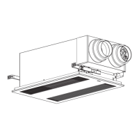
Introduction to Energy Recovery Ventilator (ERV) function and benefits.
Critical safety warnings during ceiling mount installation.
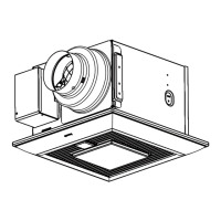
Initial steps for ceiling mount installation, including adaptor preparation.
Install suspension brackets, fix adaptor, and connect junction box and ducts.
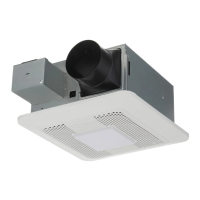
Connect outdoor hood, finish ceiling work, and mount the grille.
Optional step to attach switch labels for clearer indication.
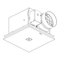
Important note regarding adaptor orientation for wall mount installation.
Install suspension brackets, fix adaptor, and connect junction box and ducts.
Finish interior wall work and mount the grille.
Optional step to attach switch labels for clearer indication.
Fill in the beginning time on the OA filter before starting the unit.
Connect power and turn on the main switch to start the unit.
Check static pressure and adjust dampers for airflow balance.
Install plug covers back when the check is complete.
Set supply (SA) and exhaust (EA) air volumes using respective knobs.
Filter and malfunction indicators provide status and alert information.
Press button after filter maintenance to reset accumulated running time.
Control power with the main switch and understand normal, defrost, and exhaust modes.
Chart showing ERV operation modes based on outdoor temperature and damper positions.
Safety precautions and warnings for performing maintenance and cleaning.
Step 1: Remove and clean the grille using mild detergent.
Step 2: Remove and vacuum-clean the OA and RA filters.
Suggestion to replace the OA filter every 6 months or as needed.
Step 3-5: Clean fan body, reinstall filters, connect power, and reinstall grille.
Technical specifications for ventilation performance, including airflow and noise.
Technical specifications for energy performance, including efficiency and transfer.
Information regarding product service, maintenance, and contact details.
| Airflow | 60 CFM |
|---|---|
| Sound Level | 0.8 sones |
| Motor Type | DC motor |
| Voltage | 120 V |
| Energy Star Certified | Yes |
| Noise Level | 0.8 sones |
| Grille Size | 13 inches square |
| Duct Diameter | 4 inches |
| Installation | Ceiling |
| Mounting Type | Ceiling Mount |