10
1
2
3
4 5 7
8
6
9
11
12
13
14
15
16
17
18
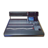
Illustrated Guide
Channel Strip – input gain controls with channel
control and status indicators. Also called a Channel
Fader Strip.
AUTOMATION/AUX LED button – selects the display
mode of the Channel Strip LED field indicators, and
arms the AUTOMATION system.
MASTER DISPLAY section – the METER and
CHANNEL buttons are direct buttons to the respective
LCD screen windows. These should be considered as
"home base" for the LCD display.
EQUALIZER section – controls for setting the
equalization parameters for a selected channel.
PAN/ASSIGN/ , BUS ASSIGN section –
controls for setting the pan and bus assignments for a
selected channel.
DYNAMICS/DELAY section – controls for setting the
onboard dynamics processing parameters for a
selected channel.
AUX section – controls for routing channels to outboard
sources and for defining the signal path as either pre-
fader or post-fader.
Display Bridge – contains the LCD screen, L/R meter
display, and primary mixer display status indicators.
BUS Fader Strip – controls for output BUSes.
MASTER L/R Fader Strip – controls for L/R MASTER
output.
Fader Layer Controls section – selects the current
fader layer to be displayed.
MONITOR section – volume and selection controls for
monitoring.
SETUP section – mixer function, or display control
buttons.
SCENE MEMORY section – buttons for writing and
reading the 50 mixer scene memories.
LIBRARY section – buttons for storing and recalling
Channel, EQ and Dynamics libraries.
Keypad – alphanumeric keys for entering numbers or
text.
Cursor Control section – buttons and controls for
defining the cursor actions.
Headset Control section – the location of the headset
connector and level control of the DA7 is immediately
below the right front edge of the Top Panel.
 Loading...