EasyManua.ls Logo

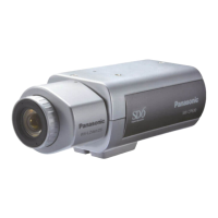
Panasonic WV-CP230

Panasonic WV-CP230
10 pages
To Next Page IconTo Next Page
To Previous Page IconTo Previous Page
Loading...
I
©
Auto
Iris
Lens
Connector
Supplies
power
and
control
signals
to
an
auto
iris
lens
(not
supplied).
©
Flange-back
Adjusting
Ring
This
ring
adjusts
the
back-focal
distance
or
picture
focus.
Rotate
this
ring
clockwise
for
a
C-mount
lens
or
counterclockwise
for
a
CS-
mount
lens.
©
Lens
(option)
©
Camera
Mounting
Screw
Hole
This
hole
is
for
mounting
the
camera
onto
a
mounting
bracket.
The
camera
is
originally
designed
to
be
mounted
from
the
bottom,
but
a
top-mounting
type
is
also
available.
To
mount
from
the
top,
remove
the
mount
adapter
from
the
bottom
of
the
camera
by
removing
two
fixing
screws.
Attach
the
mount
adapter
to
the
top
as
shown
in
the
diagram,
then
mount
the
camera
on
the
mounting
bracket.
Make
sure
that
two
original
screws
are
used
when
mounting
the
mount
adapter;
longer
type
screws
may
damage
inner
com¬
ponents.
©
Power
Cord
(only
WV-CP230)
Connect
this
power
cord
to
an
electrical
out¬
let
of
120
V
AC
60
Hz,
©
DC
12
V
Input
Terminal
(DC
12V
IN
(only
WV-CP232))
This
terminal
is
for
connecting
the
12
V
DC
power
supply
cord.
©
AC
24
V
Input
Terminal
(AC
24V
IN
(only
WV-CP234))
This
terminal
is
for
connecting
the
24
V
AC
60Hz
power
supply
cord.
©
Synchronization
Mode
Selector
(INT,
LL
(only
WV-CP230
and
WV-CP234))
Selects
the
camera
synchronization
mode
from
internal
sync
mode
(INT)
or
line-lock
mode
(LL),
INT:
Sets
to
internal
2:1
interlace.
LL:
Sets
to
Line-lock
mode.
©
Automatic
Light
Control/Electronic
Light
Control
Selector
(ALC
,
ELC)
Lets
you
select
the
mode
according
to
the
lens
type
that
is
used
with
this
camera.
ALC:
Select
this
mode
when
an
auto
iris
lens
j
(ALC
lens)
is
used
with
this
camera.
I
ELC:
Select
this
mode
when
a
fixed
iris
lens
!
or
manual
iris
lens
is
used
with
this
cam¬
era.
#
Detail/Aperture
Level
Selector
(SOFT/SHARP)
The
detail/aperture
level
can
be
selected
with
this
selector.
Set
it
to
the
desired
position
while
observing
the
picture
on
the
monitor.
SHARP:
Normal
position.
SOFT:
Select
this
position
when
a
Quad
System
is
connected
to
this
camera.
(fj)
Back
Light
Compensation
Mode
Selector
(BLC
ON,
OFF)
Lets
you
select
the
mode
according
to
the
position
of
the
object
and
light
conditions
on
the
screen.
ON:
Select
this
mode
when
a
strong
light
such
as
a
spotlight
is
in
the
background,
OFF:
Normal
picture.
@
Lens
Drive
Signal
Selector
(VIDEO,
DC)
Lets
you
select
the
mode
according
to
the
type
of
auto
iris
lens
drive
signal
to
be
sup¬
plied
to
the
lens
from
the
auto
iris
lens
con¬
nector.
VIDEO:
Select
this
mode
if
you
are
using
a
auto
iris
lens
that
requires
a
video
drive
signal.
DC:
Select
this
mode
if
you
are
using
a
auto
iris
lens
that
requires
a
DC
drive
signal.
©
Video
Output
Connector
(VIDEO
OUT)
This
connector
is
for
connecting
with
the
VIDEO
IN
connector
of
the
video
monitor.
Whenever
the
multiplexed
vertical
drive
(VD2)
signal
is
supplied
to
this
connector,
the
cam¬
era
synchronization
mode
is
automatically
set
to
Vertical
Drive.
Cautions:
*
Connect
to
12
V
DC
(10.5
V-16
V)
or
24
V
AC
(19.5
V-28
V)
class
2
power
supply
only.
Make
sure
to
connect
the
grounding
lead
to
the
GND
terminal
when
the
power
is
sup¬
plied
from
a
24
V
AC
power
source.
To
prevent
fire
or
electric
shock
hazard,
UL
iisted
wire
VW-1,
style
1007
should
be
used
for
the
DC
12
V
or
AC
24
V
Input
Terminal.
i
i

Other manuals for Panasonic WV-CP230

Related product manuals