P&H Electronics Model LA-400B Linear Amplifier
Manual Update by NA5RC Page 3 of 6
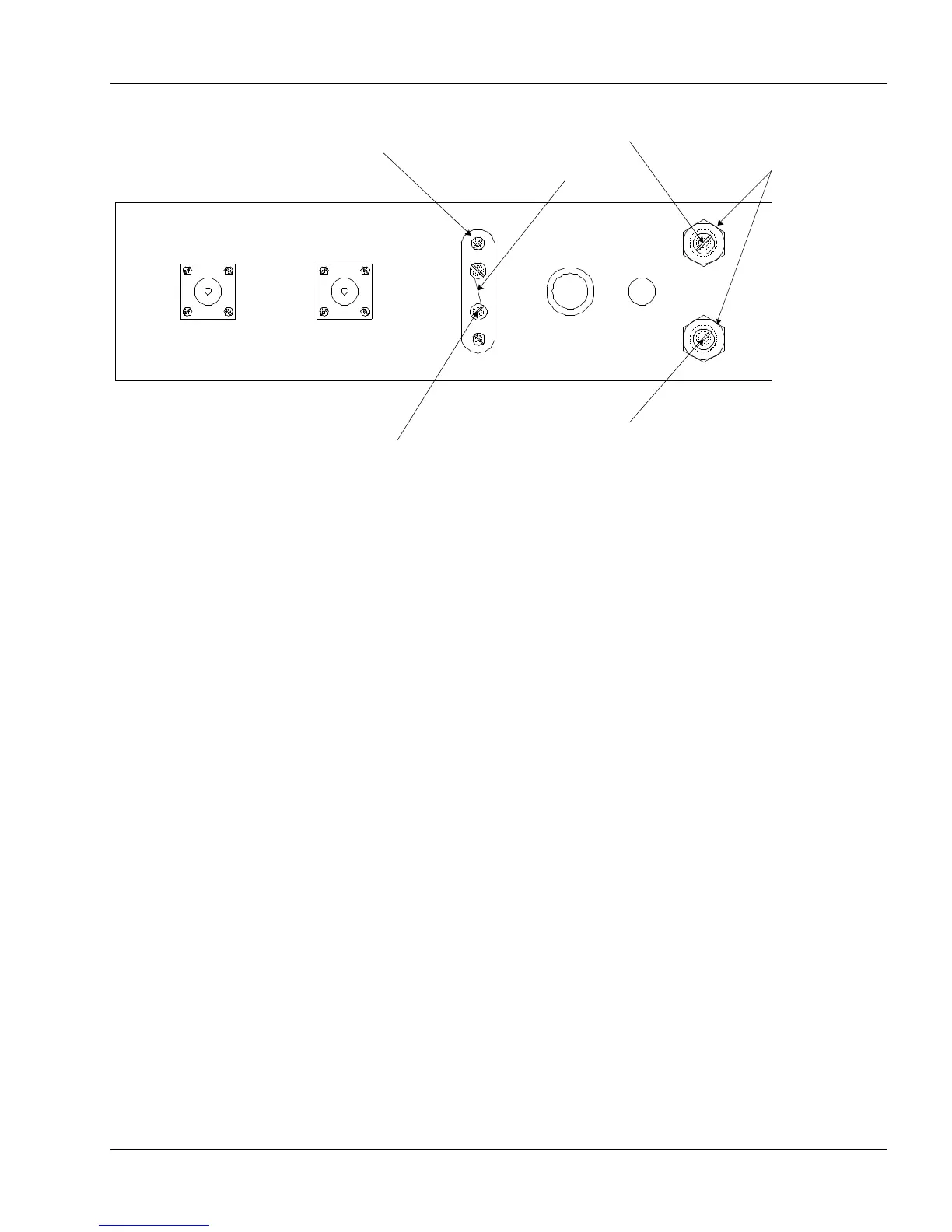
Figure 1: Chassis - Rear View
Blocking Bias
If external bias (such as from the Central Electronics 20A exciter) is used, the -100V should
be connected to terminal A on the bias strip and the jumper between terminals A and B
removed.
Where external bias is not desired, the jumper should remain between terminals A and B.
Meter Adjustments
The meter calibrating controls are preset at the factory and under normal use do not need to
be touched. However, if the RF voltage and current readings appear to be in error, they may
be checked and recalibrated in the following manner.
1. RF Voltage Input
With the meter switch set at position #1, connect a coaxial T connector to the RF input of the
LA-400B. One side of the T is connected to the exciter and the other side is connected to an
RF voltmeter, 0-50 Volts.
With carrier inserted at the exciter, the meter on the LA-400B should read the same as on the
RF voltmeter. If it does not, adjust the potentiometer marked "R.F. VOLTS" so that the two
meters read the same.
2. RF Amperes Output
With the meter switch set at position #3, connect an RF ammeter in series with the RF output
and a 52-70 Ω dummy load. Insert carrier at the exciter and note whether the RF ammeter
and the meter on the LA-400B read the same. If they do not, adjust the potentiometer
marked "R.F. AMPS" so that the two meters read the same.
 Loading...