Do you have a question about the Panduit TGJT and is the answer not in the manual?
Manually wire the TG style Jack Wire Cap, ensuring wires are slightly down over divider wedges and securing with strain relief.
Insert prepared Wire Cap into the Wire Seating/Cutting side, aligning ramp upward into the Cutter Blade Anvil groove.
Pull handle to seat conductors and trim wires nearly flush. Slide Wire Cap out; wires should cut cleanly.
Turn tool over, release trigger handle to drop scrap wires free from the tool. Ensure wire retainers contact blade anvils.
Orient the jack module retaining finger to align with the ramp and pocket of the wire cap for proper insertion.
Rotate Cam Block Housing Ram to horizontal for standard modules or vertical for older CJD-series shuttered modules.
Incorrect setting can cause non-seated caps or damage to the tool or jack module.
Pull handle closed to seat Wire Cap into Jack Module. An audible 'snap' indicates successful termination.
Inspect Wire Cap seating; retaining finger should be in place. Release trigger handle and pull completed assembly.
Order replacement kits for protector plates, blade/anvil, or blades separately to maintain tool performance.
| Type | Combination tool |
|---|---|
| Connector(s) | TG |
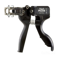
| Product color | Black |
| Quantity per pack | 1 pc(s) |
| Package type | Box |
| Dimensions (WxDxH) | 146 x 40.2 x 129.9 mm |
|---|