28
© Copyright 2008 Panoramic Corporation
PC-1000/Laser 1000 Installation
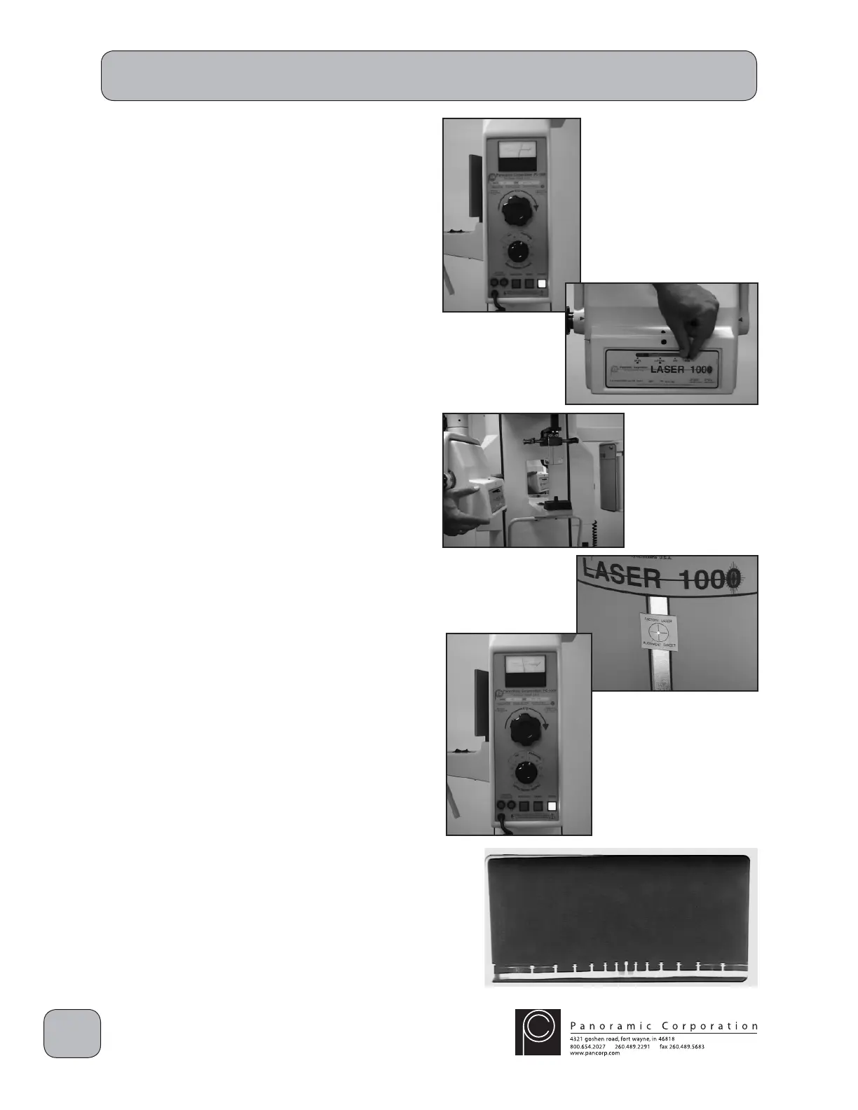
Perform Panoramic X-ray Beam Alignment
1. Power the machine on.
2. If the cephalometric arm is mounted on
the right side of the machine, using the
function switch on the control panel, select
PANORAMIC R. If the cephalometric arm is
mounted on the left side of the machine, using
the function switch on the control panel, select
PANORAMIC L.
3. Using the kVp setting knob on the control
panel, set the kVp meter to 90 kVp on the
PANORAMIC scale.
4. Slide the lever in the collimator assembly on
the front of the tubehead to the PANORAMIC
position.
NOTE: If the collimator is NOT fi rmly seated in its
locking notch:
a. the alignment laser will not fi re
b. when the exposure switch is depressed,
the machine will beep rapidly, but no
radiation will be emitted
5. Depress the laser switch on the right side of
the tubehead to activate the laser. Adjust
the tubehead so that the laser beam strikes
the the cross-hairs on the FACTORY LASER
ALIGNMENT TARGET on the fi lm drum mask.
6. Using the kVp setting knob on the control
panel, set the kVp meter to 70 kVp on the
PANORAMIC scale.
7. Place a loaded fi lm cassette sleeve on the fi lm
drum and align the L1 pointer.
8. Depress the exposure switch for the entire 12
second exposure.
9. Process the fi lm to verify proper alignment.
The fi lm should be black with clear edges.
10. Remove the FACTORY LASER ALIGNMENT
TARGET decal and install the permanent
cross-hairs target decal where the laser beam
now strikes the fi lm drum mask.
Note: Contact Panoramic Corporation if the laser
beam is no longer located within the original
 Loading...