This document is an instruction manual for PARCOL 1-6940 and 1-4640 Series Cage Control Valves, providing comprehensive details on their use, maintenance, and safety.
Function Description
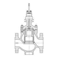
The PARCOL 1-6940 and 1-4640 Series Cage Control Valves are designed to regulate fluid flow in industrial processes. These valves typically operate with a pneumatic diaphragm actuator and are installed to allow the flow action to open the plug, unless otherwise specified. They can be installed in various positions, though vertical installation with an upward-oriented actuator is standard. The manual also covers specific configurations such as "Air-to-Close" and "Air-to-Open" actions, as well as balanced plugs with different insert types ("S", "E", "C", "D", and "R").
Important Technical Specifications
The valves are identified by a numbering system: 1 - XX 4 X.
- The first digit
1 is a constant.
XX indicates the body type: 69 for straight and 46 for angle.4 is a constant.- The last
X indicates the trim type:
1: Contoured Plug2: Contoured Plug Integral with Stem3: Multi-holes Cage8: Multi-holes Cage - Plug with Pilot
Key dimensions and tolerances are provided for various components, including:
- Nut material and tightening torque: Specified for different DN (in.) and stud types, with values for SA 194 Gr. 2H and SA 194 Gr. 8. For example, an M12 stud with SA 194 Gr. 2H requires 19 Nm, while with SA 194 Gr. 8 it requires 50 Nm.
- Valve rating and A-B (mm) dimensions: These vary by DN (in.) and valve rating, such as 150-300, 600, 900, and 2500.
- Check dimension "X" for 1-6943 series: This dimension, crucial for metallic seals, varies by port size (in.) and whether an adapter is used. For instance, a port of 8" without an adapter has an X dimension of 1.8-2.2 mm, while with an adapter it's 1.8-2.3 mm.
- Check dimension "X" for 1-6948 series: Similar to the 1-6943 series, this dimension varies by DN (in.), e.g., a 10" DN has an X dimension of 1.3-1.7 mm.
- A-B (mm) for balanced plugs: This dimension, critical for proper sealing, is specified for different port sizes (in.), e.g., 1 1/2"-2" ports require 0.9-1.8 mm, while 10"-24" ports require 2.3-3.7 mm.
The valves are designed to comply with IEC 534-3-1 standard, table 1, for face-to-face dimensions.
Usage Features
- Installation: Requires a straight pipe of at least 6 DN upstream and 3 DN downstream to prevent stream deviations. Reducers are allowed if tapered and concentric. Piping and valves must be cleaned of foreign materials before installation. Coaxiality and parallelism of piping connections are essential to avoid stress. For butt welding connections, overheating the body wall should be avoided, and the plug should be lifted over the seat if it has a plastic seal insert. The outside surface temperature should not exceed 100°C at 70-80 mm from the welding bead. Valves with threaded connections should use unions for easy removal.
- By-pass: Control valves are typically installed with a by-pass for maintenance without shutting down the process. Shut-off valves should have the same port as the pipeline, and the by-pass valve should match the control valve's port.
- Flow Direction: Indicated by an arrow on the plate.
- Actuator Position: Normally vertical with an upward-oriented actuator, but other positions are possible. Downward-oriented actuators are not recommended if the fluid contains solid particles.
- Setting Valves with Pneumatic Diaphragm Actuator: Valves are factory-set, but a further check is recommended using a pressure gauge and an air pressure regulator.
- Air-to-Close Action: Increase air pressure until the plug stops against the seat. Check that the pressure matches the specified value (2) in Figure 22 and adjust the stem/actuator connection if needed. The travel indicator should be at "0". Slowly decrease air pressure to achieve rated travel, matching value (1) in Figure 22.
- Air-to-Open Action: Increase air pressure until the plug begins to move. Check that the pressure matches value (1) in Figure 23 and adjust the stem/actuator connection if needed. The travel indicator should be at "0". Increase air pressure until rated travel is completed, matching value (2) in Figure 23.
Maintenance Features
- Safety Precautions: Only qualified staff should operate on the valve. Always isolate the valve from pressure and release pressure before any disassembly. Never approach hands to the stem and levers unless air supply is cut off and the spring is released.
- Lifting and Handling: Use eyebolts if available, or sling the valve body. Valve-actuator assembly can be lifted by actuator eyebolts only if specified on a special plate.
- Disassembly:
- Valve Type 1-6941 / 1-4641: Disconnect actuator, loosen packing, unscrew nuts, remove bonnet, and remove gasket (8). Draw out the cage with the plug by acting on the stem. If the cage is difficult to remove, strike gently around the upper end. Remove the seat (6) using threaded holes and gasket (14).
- Replacing PTFE Ring on Plug: For DN ≤ 2", remove pin (52), unscrew plug (5) from plug post (53). For DN > 2", unscrew screws (54) and remove plug post (53). Replace seal ring (51) with a new one. Tighten plug flange till metal-to-metal contact and insert pin (52).
- Valve Type 1-6942 / 1-4642: Similar to 1-6941/1-4641, but extract the plug (5) integral with the stem and remove the seat retainer (10) using threaded holes.
- Valve Type 1-6943 / 1-4643: Remove plug (5) by acting on the stem (7). Remove cage (9) using threaded holes.
- Valve Type 1-6948 / 1-4648: Extract cage (9) with plug (5) by acting on stem (7). For plug disassembly, refer to "Balanced with Pilot plugs" MAN0051E.
- Stem and Plug Replacement: Remove drill burrs. Apply grease to the new pin and slip it into the hole. Check stem and plug for alignment. Remove the pin by pushing it out with a punch. Screw the new stem in the plug using a rubber-protected pliers. Lay down the guide section of the plug into a "V" block. Drill according to Table 4 for the tool in the existing hole.
- Preparing for Reassembly: Clean all seating surfaces of metallic gaskets. For valves without metallic stop, insert gasket (8), install bonnet (2), and measure the "A" dimension. For valves with metallic stop, proceed according to relevant paragraphs.
- Balanced Plugs: Clean seating surfaces of gaskets.
- "Type S" Insert: Grease chamfer on top of the plug. Mount seal ring with the opened side up for flow from top, or down for flow from side. Tilt and gently push the seal ring into the seat. Warming the seal ring to 100°C can ease installation.
- "Type E" Insert: Grease chamfer on top of the plug. Insert O-ring on proper seat. Fit seal ring over O-ring.
- "Type C" and "Type D" Inserts: Insert first rod seal on bottom seat (49). Insert energizer (46) or (48) in central seat, then first seal ring (47) with opening at 90° to energizer, then second seal ring (47) with opening at 180° to first seal ring. Insert second rod seal (49) into top seat. Rings should be stretched minimally to avoid breaking.
- "Type R" Insert: For ports up to 2", couple seat with cage, insert plug assembled with flange (111), washer, and ring nut (113) without c-ring seal. Measure from top of cage to ring nut (dimension A). Repeat with c-ring seal (dimension B). If A-B difference is within Table 12, tighten ring nut and bend washer (114). For ports 3" and over, first couple seat with cage, insert plug assembled with flange (111) without c-ring seal. Measure from top of cage to ring nut (dimension A). Repeat with c-ring seal (dimension B). If A-B difference is within Table 12, tighten nut (112) and bend washer (114).
- Disposal: Dispose of the valve and components securely according to local, national, and international regulations. Separate components into electrical/electronic and ferrous scrap. Refer to relevant instruction manuals for electrical/electronic component disposal. Check local regulations for waste disposal.