4. TECHNICAL DATA
Model
Engine type
Self-Propelled
Engine Displacement
Nominal Power
Blade Width
Rated Speed
Fuel Tank Capacity
Grass catcher
capacity
Net Weight
Height adjustment:
9696093
DG450
yes
135 cm
2.4kW
460mm
2800/min
1.2L
60L
35kg
25~75mm 10 adjustment
3
Model
Guaranteed Sound pressure level
at operator's position
(According to EN ISO 5395-1 Annex F &
EN ISO 5395-2, EN ISO 4871)
Measured sound power level
Guaranteed Sound Power level
(According to 2000/14/EC)
Vibration
(According to EN ISO 5395-1 Annex G &
EN ISO 5395-2)
DT-807856
83 dB (A)
(K=3 dB (A))
93dB(A)
K=2.02dB(A)
96dB(A)
6.22m/s²
K=1.5 m/s²
5. ASSEMBLY
5-1 ASSEMBLY THE FOLDING HANDLE
A) Fix the lower handlebars into the unit body with locking knobs. (Fig.2A/2B/2C)
B) Release the upper handlebars for folding. Connect the upper handle and the lower handle with
the locking knobs. (Fig.2D)
C).Attach the cable clamps to the position shown and then attaches the cable.(Fig.2E/2F)
Fig. 2A Fig. 2B
Fig. 2C
Fig. 2D
Fig.2E left handle Fig.2F right handle for self-drive control cord
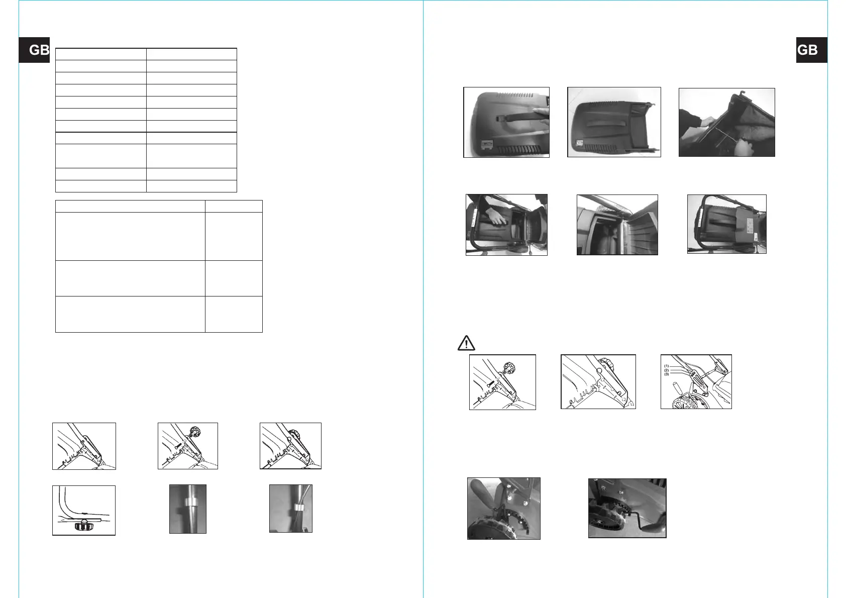
5.2 MOUNTING AND DISMOUNTING THE GRASS CATCHER
Assemble the handle into the grass catcher. (Fig.3A/ Fig.3B/ Fig.3C)
Insert one end with a projection into the grass catcher, and then fixed another end of the handle
onto the grass catcher with the screw. ST4.8*19.
Fig. 3A Fig. 3B
Fig. 3C
Fig. 3D Fig. 3E Fig. 3F
1. To fit: Raise the rear cover and hitch the grass catcher on rear of mower. (Fig.3D/Fig.3E/Fig.3F)
2. To remove: Grasp and lift the rear cover, remove grass catcher.
5-3 ADJUSTMENT FOR AN APPROPRIATE THE HEIGHT
1. Back out the locking knobs which fixed the lower handle. (Fig.4A/Fig.4B)
2. Refer to Fit.4C, move the lower handle up and down, adjust it to the proper height. There is 3
adjusting height to be choose on this type lawn mower; at 1 height, lower handle to the ground is
highest, 3 height is the lowest.
3. Adjusting to the proper height, then fix the lower handle by the locking knobs.
WARNING: The left side and right side of lower handle must adjust to the same height.
Fig. 4A Fig. 4B
Fig. 4C
5.4 ADJUSTMENT OF CUTTING HEIGHT
Apply outward pressure to disengage lever from rack. Move lever forward or back to adjust height.
The height (the blade to the ground) can be adjusted from 25mm (position 1) to 75mm (position
10), 10 height positions.
Fig.5A Position 10 Fig.5B Position 1
65
 Loading...