Do you have a question about the Parker 10MFP and is the answer not in the manual?
Filtering new fluid before putting it into service for optimal system performance.
Transferring fluid from drums or storage tanks to system reservoirs for clean transfer.
Conditioning fluid that is already in use to maintain cleanliness levels.
Complimenting existing system filtration to enhance overall performance.
Removing free water from a system to prevent damage and ensure fluid integrity.
Designed for use with fluids such as hydraulic, gear, and lube oils.
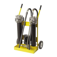
Top-accessible for easy changing of filter elements.
Two-stage, double-length filtration for long element life and pump protection.
Industrial quality, quiet operation, and dependable long life.
Available for particulate and Water Removal (WR) with increased DHC.
Ready to use with flexible hoses for tight spots and kink resistance.
Indicates when the filter element needs to be changed.
Rugged construction designed to be durable and last.
Industrial brand motor for reliable power.
Helps keep the work area safe and clean.
6 ft. cord with ON/OFF switch and optional plug types.
Specifies the viscosity range for optimal fluid handling.
Differential pressure type with 3-band status: clean, change, bypass.
Integral to element: Inlet 3 psid, Outlet 35 psid.
Unit operates from -40°F to +150°F (-40°C to +66°C).
Requires 10MFP-110/220 volts, 60/50 Hz, single phase, 10/5 amps.
10MFP motor is 3/4 hp @ 3450 rpm with thermal overload protection.
Details materials used for cart frame, filter head, bowl, hoses, and wands.
The portable filter cart weighs 110 lbs. (45.4kg).
Provides overall Height, Width, and Depth measurements in mm and inches.
Recommended ISO cleanliness level for servo control valves.
Recommended ISO cleanliness level for proportional valves.
Recommended ISO cleanliness level for vane and piston pumps/motors.
Recommended ISO cleanliness level for control valves.
Recommended ISO cleanliness level for gear pumps/motors.
Recommended ISO cleanliness level for flow control valves and cylinders.
Typical ISO cleanliness level for new fluid as received.
Thread hose end with straight thread o-ring seal fitting into filter flange.
Connect wands to swivel fitting; avoid over-torque on PVC coupling.
Place into supply fluid receptacle; RFP filter is the inlet filter.
Place into clean fluid receptacle; ILP filter is the outlet filter.
Ensure switch is OFF and plug cord into proper grounded power source.
Check outlet wand for oil flow; allow 30-60 seconds for filters to fill.
Turn switch to OFF and unplug cord from electrical outlet.
Remove wands from oil to prevent siphoning during servicing.
Loosen hex head screws, turn cover to clear, then remove.
Pull element from head; replace synthetic/Microglass, clean wire mesh.
Ensure o-rings seat properly and notch aligns with head.
Inspect the cover o-ring and replace if necessary.
Tighten screws until snug; do not over-torque. Do not interchange covers.
Lists part numbers, supersedes, models, options, and replacement elements for standard products.
Details part numbers, micron rating, media type, seal type, and integral bypass for elements.
Lists replacement elements for the 10MF Filtration Trolley.
Handheld, lightweight, compact design fits easily on 55-gallon drums.
Features Carboxylated Nitrile seals, handles high viscosity fluids.
No downstream fluid bypass ensures 100% filtration.
Offers high capacity 2 micron absolute disposable microglass to 74 micron cleanable wire.
Clear, wire-reinforced 5' hoses with wand attachments, ready to use.
Optional quick disconnect hose connections for fast setup and tear-down.
Motor with thermal overload protection, replaceable brushes.
Dirt tolerant design with visible serviceable inlet strainer and quiet operation.
Low center of gravity, dual motor seals for added protection.
Ports for flexible use, outlet can serve as a sampling port.
MAOP is 50 psi (3.4 bar).
Unit has a flow capacity of up to 4 gpm (15 lpm).
Handles viscosities up to 16,000 SUS (11,000 SUS for 24VDC).
Warning against pumping flammable liquids like gasoline, alcohol, solvents.
Unit: -15°F to 180°F; Wand/Hose: 25°F to 120°F.
Differential pressure type indicator, set at 25 psid.
Suitable for petroleum oils, water emulsions, and diesel fuels.
Set at 50 psi for motor protection.
Rated at less than 70db at 3 feet.
1/4 hp motor with thermal overload and replaceable brushes.
Approximately 23 lbs. 5 oz.
Lists materials for housing, cover, handle, wands, hose, fittings, and seals.
Remove all shipping plugs from hoses and fittings before use.
Connect inlet/outlet hoses and wand assemblies.
Insert inlet wand into fluid to be filtered or transferred.
Insert outlet wand into container for fluid discharge.
Plug in the unit and flip the switch to the 'on' position.
Turn unit off and disconnect the electrical plug before servicing.
Rotate cover counter-clockwise and remove to access element.
Discard disposable elements; install new element fitting o-ring.
Inspect the cover o-ring and replace if necessary for proper seal.
Replace cover, hand-tighten screws until snug; do not over-torque.
Lists part numbers and box quantities for various filter media types.
Provides part numbers for all components of the Guardian unit assembly.
Select seal type symbol: None (Carboxylated Nitrile Standard).
Select model symbol: GT4, GT4D, GT4E for voltage options.
Select filter media symbol: 74W, 40W, 25W, 10C, 20Q, 10Q, 05Q, 02Q, WR.
Select option symbol: 1 (None) or 6 (Quick disconnect hose connections).
| Brand | Parker |
|---|---|
| Model | 10MFP |
| Category | Outdoor Cart |
| Language | English |