- 3 -
4. Switching functions
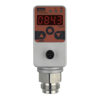
Hysteresis function:
If the system temperature
fluctuates around the nominal
value, the hysteresis keeps the
switch status of the outputs
stable. When the system
temperature is rising, the output
switches when it reaches the
respective switching point (SP); if
the pressure falls again, the
output switches back only if the
reverse switching point (rSP) is reached.
(See menu point
FunC, SP,rSP)
Window function
The window function allows
the monitoring of a defined
range.
If the system temperature
is between the switching point
(SP)and the reverse switching
point (rSP),
the output is activated.
(See menu point FunC,SP,rSP).
Error function
Switch output 2 can be used optionally as an error output
to display temperature switch function errors. As an error
output it is normally closed, and in case of errors (
Err1 ,
Err3 ) it is open. At the same time LED II lights up. The
display and the error output remain active until the error is
cleared. (See menu point Err)
It conforms to DESINA when used with
a 4-pole M12x1 connecting plug
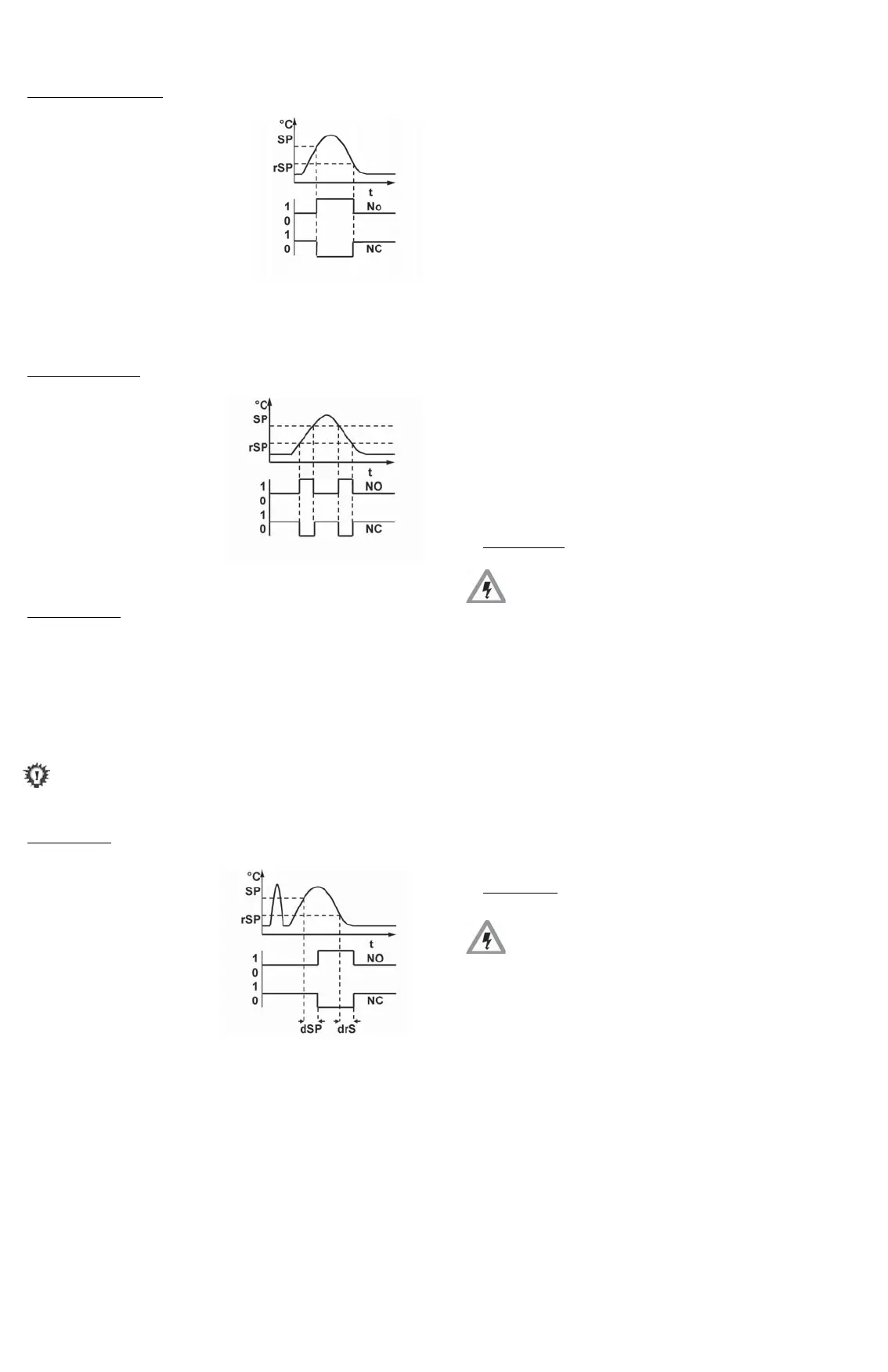
Delay times (0 to 99,9 secs.)
The temperature must remain
for at least this time to enable
the switch to operate. The switch
output does not immediately
change its status when it
reaches the switching event,
but only after the delay time has
elapsed. If the switching event
no longer pertains when the
delay time has elapsed, the
switch output does not change.
(See menu points
dSP and drS)
- 4 -
5. Analogue Output
The temperature switch has two standardised output
signals from 0-20mA or 4-20mA. In addition, it is possible
to calibrate the starting and end values.
This is a prerequisite for
n compatibility with existing systems
Examples:
An output signal from 4-20 mA
for -40°C up to 125°C is required.
Resultant setting values for e.g.:
AnA = 4-20 Analogue output 4-20 mA
(see menu point AnA)
FroM = -40 -40°C = 4 mA
(see menu point FroM)
to = 125 125°C = 20 mA
(see menu point to)
6. Installation
Mechanical:
Install and de-install the temperature switch only
when there is no pressure present.
Attach the temperature switch to the appropriate process
connection. Installation should be undertaken only across
flats spanner.
Ensure that the digital display is placed in the best viewing
position by using the rotational housing adjustment.
The housing can be attached
n with self-tapping screws into two blind holes at the
back of the housing
n with clamps
A safety sleeve is required to protect the sensor against
higher pressure or aggressive mediums/substances.
Electrical:
The temperature switch may be installed only by
a qualified electrician in accordance with the
respective national and international regulations.
Protect the temperature switch from electromagnetic
influences and over-voltages.
Optional installation tips which are shown by experience to
reduce the influence of interference:
n Use shorter cables
n Avoid short distances between connecting leads and
power consuming devices and interference-
generating electrical and electronic equipment.
n Use free running diodes
 Loading...