www.parweld.co.uk
7
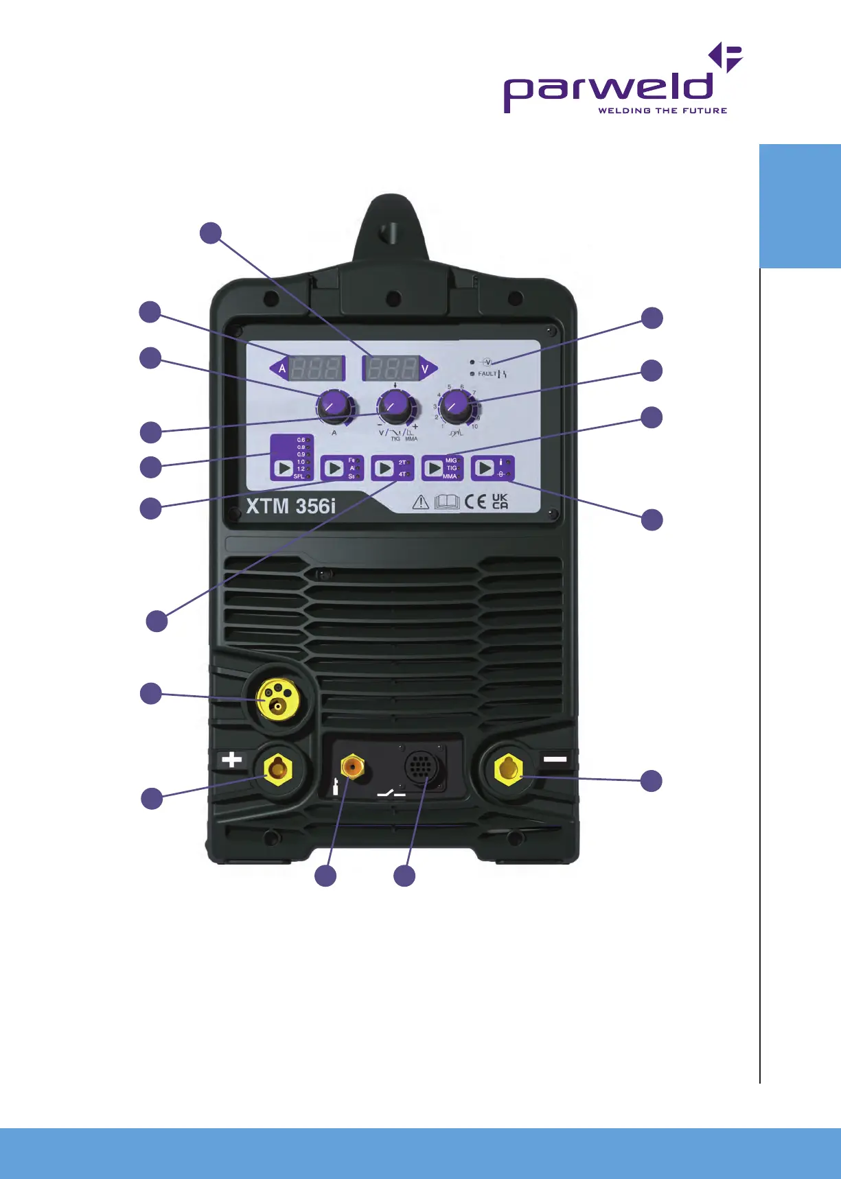
MACHINE
OVERVIEW
1. Voltage Display. Displays the welding voltage during welding.
2. Amperage Display. Displays the welding amperage or wire
speed during welding.
3. Amperage control for adjusting the Amperage (wire feed speed).
4. Voltage control This function controls the MIG welding voltage.
It can be adjusted in nitely within the working voltage range.
5. Wire Diameter/Manual MIG selector.
6. Material Type Selector (MIG).
7. Latching trigger selector. 2T denotes momentary trigger,
4T denotes latching trigger.
8. MIG torch euro connector, for connection of the MIG torch.
9. Positive Output Connection for MMA or TIG.
10. Power Indicator shows when the machine is turned on.
11. Inductance control, this hardens or softens the arc in MIG
welding.
12. Process Sector MIG, MMA or TIG.
13. Gas test and wire inching button.
14. Negative output connection used to connect the work return
cable. This is the 50mm Dinse connection socket.
15. Gas connection for TIG welding (TIG torch is optional extra).
16. Trigger connection for TIG welding (TIG torch is optional extra).
4.1 Description of Controls Front
1
2
3
4
5
6
7
8
9
15 16
14
13
12
11
10
 Loading...