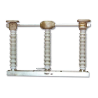
The spacer is to be discarded after the coupling
is clamped around the VOP. Do not tighten the
piercing bolts at this time since the relative
positions of the OPEN and CLOSED position
indicators may need to be moved.
Coupling with position indicators
NOTICE: IT IS RECOMMENDED TO USE SILICON ON THE BACK OF THE ENCLOSURE
WHERE IT MEETS THE STRUCTURE AFTER THE MO-10 HAS BEEN MOUNTED. THE FOUR
SEALING WASHERS ATTACHED TO THE MOUNTING BOLTS ON THE BACK OF THE MO-10
SHOULD BE PLACED ON THE BOLT BETWEEN THE STRUCTURE AND THE CABINET PRIOR
TO MOUNTING WITH THE NEOPRENE SIDE OF THE WASHER FACING THE CABINET.
Use the manual crank handle and crank the
switch to the fully OPEN position. Set the
“open limit” Auxiliary Switch 1 according to
the yellow decal.
Now that the “closed”, “open” and dynamic
brake auxiliary switches have been set and with
the switch still in the OPEN position, uncouple
the vertical operating pipe from the motor
operator. Slide the pin through the coupling so
that the uncoupling bar is held in the uncoupled
position.
Electrically operate the motor operator to the
CLOSED and back to the OPEN position. Try
to couple the VOP to the motor operator. The
uncoupling bar should slide freely into the slot
on the fixed coupling. If it does not, manually
crank the motor operator to where it does couple
freely and reset the “open” Auxiliary Switch 1.
Uncouple the VOP and repeat the process until
the uncoupling bar will operate freely without
manually cranking the motor operator.
Couple the VOP to the motor operator and
manually crank the switch to the fully CLOSED
position. Uncouple the VOP and electrically
operate the motor operator and adjust Auxiliary
Switch 2 until the uncoupling bar slides freely
into the fixed coupling slot.
Couple motor operator to the VOP and
electrically operate switch to verify appropriate
setting of the cams. Reset limit switches as
necessary.
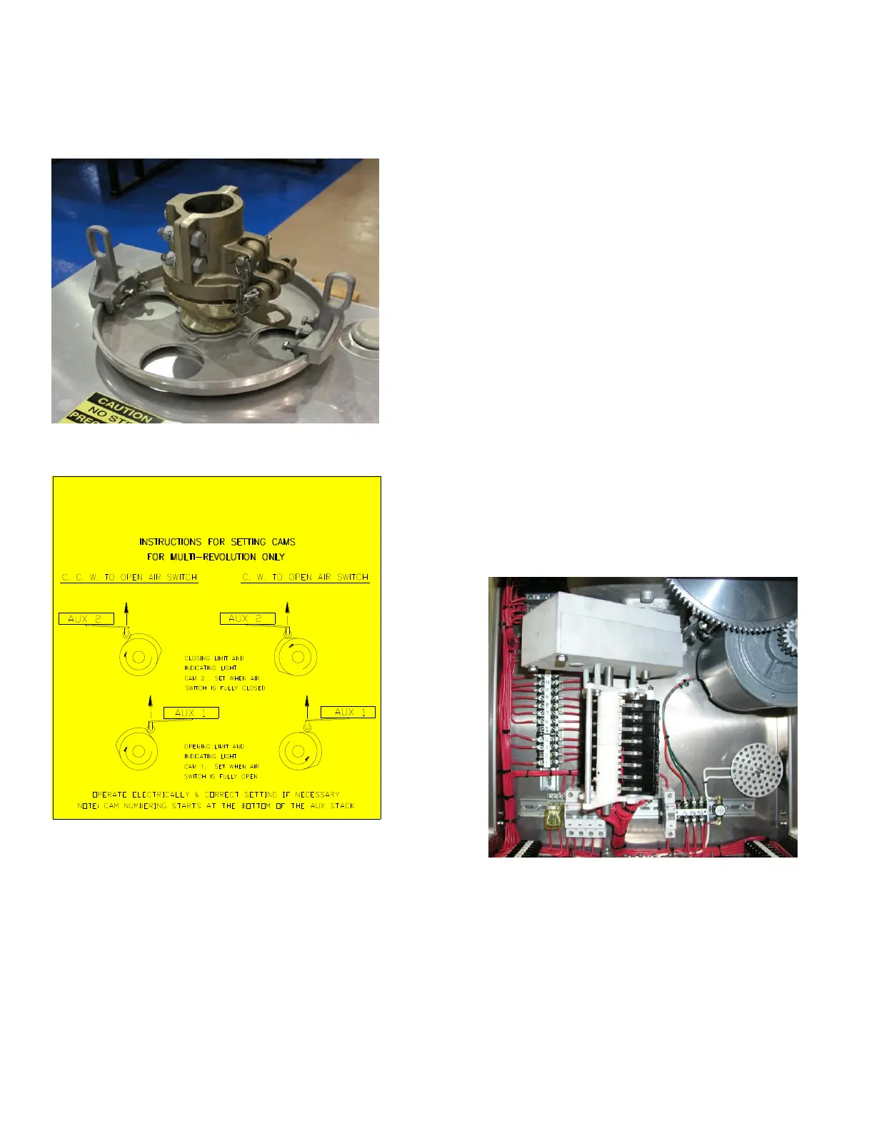
Once successful switch operation is achieved
the remaining auxiliary switches can be set as
required.
View showing auxiliary switches with
individually set cams.
Braking of the permanent magnet motor is
accomplished through a braking resistor located
on the back side of the gear cover panel.
 Loading...