EasyManua.ls Logo

Pavone Sistemi DAT 500 User Manual

Pavone Sistemi DAT 500
59 pages
To Next Page IconTo Next Page
Page #1 background imageLoading...
Page #1 background image
Pavone Sistemi
pesatura elettronica industriale
TECHNICAL MANUAL
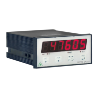
DAT 500 Weight Indicator/Transmitter with serial and ANALOG output
Software version PW13012

Questions and Answers:

Pavone Sistemi DAT 500 Specifications

General IconGeneral
CategoryAccessories
ProducerPavone Sistemi
Power Supply12-24 VDC
ProtocolsModbus RTU, ASCII
Digital Inputs4
Digital Outputs4
Input Channels1
DisplayLCD
Serial PortsRS232, RS485
Analog Output0-10V or 4-20mA
Weighing FunctionsTare, Total
EnclosureABS
MountingPanel, DIN Rail
Communication InterfaceRS232, RS485
Operating Temperature-10°C to +40°C
Load CellsUp to 8 load cells 350 Ohm

Summary

PRECAUTIONS

INTRODUCTION

TECHNICAL FEATURES

INSTALLATION

OVERALL DIMENSIONS

Provides the physical dimensions and mounting cutout for the DAT 500 instrument.

ELECTRICAL AND POWER SUPPLY

Details on electrical connection requirements and instrument power supply information.

FRONT PANEL OF THE INSTRUMENT

DISPLAY AND LED INDICATORS

Explains the 6-digit display and the meaning of the four LED indicators on the instrument panel.

USING THE KEYBOARD

INFO DISPLAY

ERRORS NOTIFICATION

Lists and explains error codes that may be displayed by the instrument.

VIEWING, ZEROING, AND SELF-CALIBRATION

VIEWING WEIGHT MODES

Explains how to switch between viewing net and gross weight on the display.

CALIBRATION FUNCTIONS

Details conditions and procedures for self-calibration and zeroing the instrument.

PEAK FUNCTION

PROGRAMMING THE WEIGHT SETPOINTS

KEYBOARD LOCK/UNLOCK FUNCTION

SWITCHING THE DISPLAY OFF

SETTING

GENERAL DATA

Overview of the setup menu and how settings are stored and defaulted.

CHANGING AND ENTERING THE PARAMETERS

Guides on accessing and navigating the setup menu and parameter settings.

DIAGRAM OF THE MENU

QUICK SET-UP

SETTING PARAMETERS

SYSTEM AND CELL CONFIGURATION

Configures system capacity (CAPAC, NETE) and load cell sensitivity (SENSE).

CALIBRATION AND DIVISION SETTINGS

Sets fixed calibration (DEAD L) and system division value (dSPdIJ).

DIAGNOSTIC AND MODE SETTINGS

Configures load cell signal display, A/D converter test, and operating mode.

UPLOAD RECEIVING DATA FUNCTION

SENDING DATA FUNCTION

EXAMPLE OF SETTING/CALIBRATION

CALIBRATION

ZERO CALIBRATION

Procedure for zero calibration when the scale is unloaded and stable.

CALIBRATION OF FULL SCALE

Procedure for calibrating the full scale using sample weights.

EXIT FROM CALIBRATION MENU

Instructions on how to exit the calibration menu and save settings.

LINEARIZATION PROCESS

WEIGHTING PARAMETERS

WEIGHT FILTER

Adjusts the refresh speed for display and serial/analog output.

WEIGHT STABILITY

Defines the number of divisions needed to consider the weight stable.

AUTOZERO UPON SWITCHIN ON

Sets the maximum resettable weight upon instrument startup.

TRACKING THE ZERO

ZERO BAND

INPUT/OUTPUT PARAMETERS

SETPOINT 1 CONFIGURATION

Configures setpoint 1 mode, hysteresis, timing, and delay.

SETPOINT 2 CONFIGURATION

Configures setpoint 2 mode, hysteresis, timing, and delay.

LOGIC INPUT/OUTPUT TESTING

Procedures for testing logic inputs and outputs.

SERIAL OUTPUT PARAMETERS

COM1 SERIAL CONFIGURATION

Configures baud rate, protocol, and address for COM1 serial port.

COM2 FIELDBUS CONFIGURATION

Defines COM2 Fieldbus protocol and programs its address.

COMMUNICATION PROTOCOLS OVERVIEW

Covers Continuous, Manual, Slave, and Modbus RTU protocols.

ANALOG OUTPUT PARAMETERS

ANALOG OUTPUT CONFIGURATION

Configures analog output full scale, mode, and range.

ANALOG OUTPUT TEST AND CALIBRATION

Tests analog output operation and calibrates the offset.

SERIAL COMMUNICATION PROTOCOLS

TRANSMISSION PROTOCOL TYPES

Describes Continuous, Automatic, and Manual transmission protocols.

SLAVE TRANSMISSION PROTOCOL

Details the controls and command format for the SLAVE transmission protocol.

MODBUS RTU PROTOCOL

Explains Modbus RTU protocol, functions, registers, and configuration.

PRINT PROTOCOL

PRINT FUNCTIONALITY

Details print command activation and required conditions.

PRINTER CONNECTION AND FORMATS

Shows printer connection diagram and report format examples.

UPLOAD AND DOWNLOAD FUNCTIONS

CONFIGURATION TRANSFER PREPARATION

Steps to prepare the instrument and PC for configuration transfer.

DATA TRANSFER METHODS

Explains how to upload and download instrument configurations.

TROUBLESHOOTING

DECLARATION OF CONFORMITY

Related product manuals