EasyManua.ls Logo

pcl NEXUS User Manual

pcl NEXUS
60 pages
To Next Page IconTo Next Page
Page #1 background imageLoading...
Page #1 background image
www.pclairtechnology.com
NEXUS Nitrogen Generator Only User Manual
Safety Guidelines
This manual contains information that is very important to know
and understand. This information is provided for safety and to
prevent equipment problems. To help recognise this information,
observe the following symbols.
Danger indicates an imminently hazardous
situation which if not avoided WILL result
in death or serious injury.
Warning indicates a potentially hazardous
situation which if not avoided, COULD
result in death or serious injury.
Caution indicates a potentially minor or
moderate injury.
Notice indicates important information,
that if not followed, may cause damage to
equipment.
Unpacking
After unpacking the unit, inspect carefully for any damage that
may have occurred during transit.
Do not operate unit if damaged during
shipping, handling or use.
General Safety Information
The operator of this product must take the necessary precautions
to prevent the level of danger indicated by these symbols. The
operator is required to read and understand this instruction
manual and all safety warnings, labels etc.
Any employer allowing the use of this product in their field of work
must distribute this instruction manual to all users. The employer
must also ensure all users read, understand and follow the
instructions as described in the manual, safety warnings, labels,
etc.
Please read and save these instructions. Read carefully before attempting to assemble, install, operate or maintain the product described.
Protect yourself and others by observing all safety information. Failure to comply with instructions could result in personal injury and/or
property damage! Retain instructions for future reference.
Image shown is PCL standard decal.
Actual decal may vary by individual part number.
Read and understand all safety warnings
and instructions before operating this
product. Failure to read and follow all
safety warnings may result in serious
personnel injury or death. Property
damage and/or product damage may also
occur if all warnings are not followed.
1. Do not expose the product to flammable gases,
vapours or fumes
2. Do not store flammable gases in or near this product
3. Never use flammable or toxic solvents to clean the
product or any of the unit's parts
4. Never remove or alter any safety warning labels, tags,
etc. located or provided with product.
5. Follow all directions for maintenance.
The use of other than genuine PCL
replacement parts may result in reduced
equipment performance. Repairs must be
performed by authorised repair personnel,
otherwise the warranty will be void.
PART NUMBER
SERIAL NUMBER
76404
Question and Answer IconNeed help?

Do you have a question about the pcl NEXUS and is the answer not in the manual?

pcl NEXUS Specifications

General IconGeneral
Fuel TypeGasoline
Power Output120V
Starting SystemRecoil
Engine Type4-stroke OHV
Outlet Types2x 120V 20A

Summary

Safety Guidelines

DANGER Symbol and Meaning

Indicates an imminently hazardous situation that WILL result in death or serious injury.

WARNING Symbol and Meaning

Indicates a potentially hazardous situation that COULD result in death or serious injury.

CAUTION Symbol and Meaning

Indicates a potentially minor or moderate injury.

NOTICE Symbol and Meaning

Indicates important information that may cause damage to equipment if not followed.

General Safety Information

Operator Responsibility

Operator must read and understand manual. Employer must ensure users read and follow instructions.

Key Safety Instructions

Read warnings before operating; avoid flammable gases, solvents, and alter warning labels.

Unpacking

Inspect for Transit Damage

Inspect unit carefully for any damage that may have occurred during transit.

Warning: Do Not Operate If Damaged

Do not operate unit if damaged during shipping, handling or use.

General Specifications

NEXUS Variants Specifications

Details specifications for NEXUS variants including inlet pressure, supply, and cut off pressure.

Guidelines

Power Supply Requirements

Connect power supply from main switchboard with MAX 3amp fuse/RCB protection. Must be grounded.

Air Supply Filtration and Pressure

Ensure compressor has filtration and air supply is 10 psi above max inflation range.

Inside Installations

Electrical Connection Requirements

Use 3 pin plugs or 2 pin + Earth with Earth Ground wire installed on electrical infrastructure.

Pre-use Installation Elements

Included Installation Components

List of hardware included for pre-use installation: foam insert, hoses, brackets, gauge, screws.

Installation Steps

Install Filter-Regulator Unit

Install filter-regulator and dial gauge, applying PTFE tape to threads before screwing.

Mount Filter-Regulator Brackets

Locate and mount brackets to cabinet side using provided screws and washers.

Attach Pneumatic Pipe

Connect pneumatic pipe to the right hand side of the filter-regulator via a push-in fitting.

Install Hose Mounting Hooks

Mount hose mounting hooks on cabinet sides using provided screws and washers.

System Set-up Instructions

Output Port Connection Warning

Ensure output port is connected using Rp 1/4 fitting to prevent pressure exhaustion.

Connect Air Supply Input

Connect to air supply using Rp 1/4 fitting into the compressed air inlet port.

Connect Mains Power

Connect mains power lead to the IEC socket at the back of the unit.

Power On and Operation Readiness

Turn unit on; it's ready when tank pressure reaches 8bar/116psi.

Service and Maintenance

Non-Serviceable Components

Pressure transducer and electric control board require qualified replacement.

Periodic Maintenance Checks

Periodically check hoses, tyre connectors, and clean sintered filters.

Working Safety Instructions

Hazardous Area Installation

Do not install in areas where explosions are possible as unit is not explosion-proof.

Risks of Improper Use

Product can be dangerous if used improperly; children should not use; risk of tyre burst.

General Safety Compliance

Operator must understand manual. Use only for air/N2 dispensing. Modifications void warranty.

Unit View

Component Identification

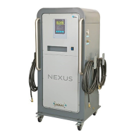
Identifies key components like handles, display, ports, and castors on the unit.

Unit Features

Nitrogen Pressure Gauge

Located on the side, indicates the Nitrogen tank pressure contained within the unit.

Nitrogen Purity Test Port

Located on the side, used to identify the purity of Nitrogen produced by the machine.

Auxiliary Port Details

Bottom left port for connecting other equipment; requires pressure drain before use.

For Trained Engineers Only

Accessing System Diagrams

Instructions for accessing system installation and internal wiring diagrams in a document wallet.

Nitrogen Tank Contents

Display Readings Explained

Display shows internal Nitrogen TANK pressure, NOT tyre pressure. Flashes between pressure and 'n2'.

Example Operation Sequence

Illustrates display readings during inflation: pressure changes and 'n2' status.

Troubleshooting Guide

Common Problems & Solutions

Lists common issues like 'No display' or 'Low pressure' with causes and solutions.

Error Codes and Resolution

Details specific error codes (E1-E28), their causes, and required actions like PCB replacement.

PCL Limited Warranty

Warranty Coverage and Period

Covers defects for 12/18 months. Excludes hoses. Repair/replace defective parts.

Warranty Claim Process

Requires timely notice, proof of purchase, serial number, and proper packing of returns.

Warranty Exclusions

Excludes routine maintenance, improper use, damage, wear and tear, corrosion.

Warranty Registration

Form to complete and mail or visit website to activate warranty.

Calibration Certificate

Calibration and Traceability

Unit checked and calibrated on test equipment traceable to UKAS Laboratory No. 0221.

EC Directives and Standards

Confirms compliance with EMC, Low Voltage directives, and emission/immunity standards.