Rear Fuselage Construction (Booms)
To arrive at the DV8R’s uniquely shaped fuselage, we have devised a method that
allows you to build the fuselage in three separate sections and then these are brought
together for final assembly much like a full scale aircraft is built. IMPORTANT: It is
very strongly recommended that you closely follow the instructions as we present them
here in order to construct the model correctly. We have spent much time devising these
methods and they are PROVEN to work!
You are going to build two separate sections for the rear of the fuselage and then you
will construct the front section of the model as a single unit. It goes without saying that
the parts provided can be assembled as either a left or right so it is all to easy to forget
that you need to reverse your construction techniques to build the model properly so we
will conclude with the following.
VERY IMPORTANT: BE SURE OF THE ORIENTATION OF ALL PARTS
BEFORE FINAL GLUING ☺
We begin by constructing one tail boom section; in the photos you will see both booms being
constructed so you may begin with either side but it would be best to finish one then go back and
build the other.
Locate the two motor mounts (MM) and
two ½ x 3/8 x 4 Hardwood Blocks and
epoxy or CA them securely to the sides of
the motor mounts flush with the opening
as shown.
Remember to make a left and right.
Locate formers FF 5 and FF 6 and a length
of the ½ x ½ x 36 balsa triangle stock
Study the following photos to get an idea
as to how the balsa triangle stock is
oriented onto the formers to allow them to index with the other pieces that will be used in the
next steps.
Use CA to glue the balsa triangle to the
formers as shown and leave overhang at the rear.
This will be sanded flush later.
7
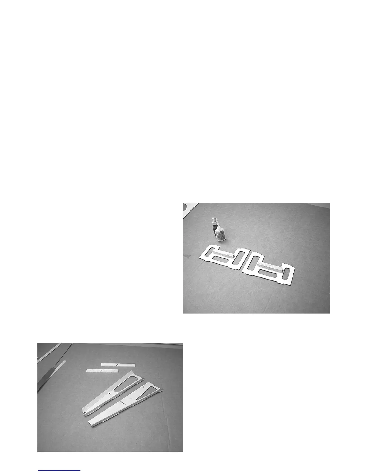
Cut a seven-inch and an eight-inch section of
½ balsa tri stock. These pieces will be placed
forward and aft of the stabilizer spar at the joint at
the bottom of former FF6.
 Loading...