ISSUED: 07-25-11 SHEET #: 090-9203-1
5 of 6
Visit the Peerless Web Site at www.peerlessmounts.com
For customer care call 1-800-865-2112
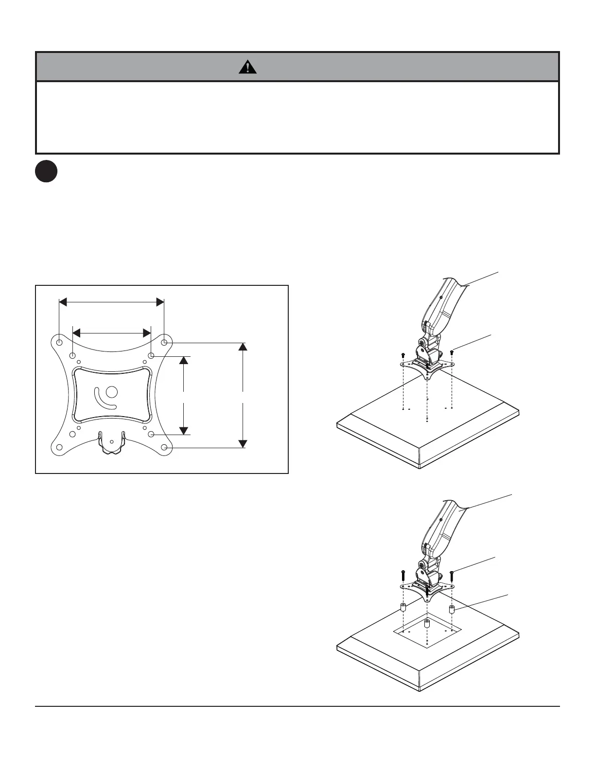
Attaching Arm Assembly to Screen
To prevent scratching the screen, set a cloth on a fl at, level surface that will support the weight of the screen.
Place screen face side down. If screen has knobs on the back, remove them to allow the arm assembly to be
attached. Place arm assembly (B) on back of screen.
Choose hole pattern as shown in detail 1.
FOR DISPLAYS WITH FLAT BACKS: Attach arm assembly (B) to display using four 12mm screws (F or H) as
shown in fi gure 4.1.
FOR DISPLAYS WITH RECESSED BACKS: Attach arm assembly (B) to display using four 30mm screws (G or
I) and four spacers (J) as shown in fi gure 4.2.
• Tighten screws so arm assembly is fi rmly attached. Do not tighten with excessive force. Overtightening can cause
stress damage to screws, greatly reducing their holding power and possibly causing screw heads to become
detached. Tighten to 40 in. • lb (4.5 N.M.) maximum torque.
• If screws don't get three complete turns into the screen inserts or if screws bottom out and arm is still not tightly
secured, damage may occur to screen or product may fail.
WARNING
VESA 100mm
VESA 75mm
VESA 75mm
VESA 100mm
DETAIL 1
4
B
B
G,I
J
F,H
fi g. 4.1
fi g. 4.2