Do you have a question about the Pegasus PP-6750V Series and is the answer not in the manual?
Details key time recording capabilities like capacity, LCD display, duty codes, and alarm schedules.
Outlines system parameters, personal access maps, operation modes, and data output.
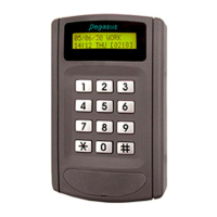
Details the format of date, time, weekday, and parameter displays on the LCD.
Explains the meaning of indicators like REP, MOT, DPT, and buffer counters on the second and third displays.
Identifies and explains the LCD display and status LEDs on the device panel.
Details the various connectors (JP1, J2, J4, J5, J6) on the bottom of the device.
Lists the pin functions for the 9-pin blue connector (J2), including power and access control.
Details the pin functions for the 8-pin white connector (J1) for interface and alarm output.
Shows wiring for access control with an electric strike, including J2 pin connections.
Illustrates wiring for heavy load locks like magnetic or drop bolt locks using J2.
Details wiring connections for 8F and 24F relay boxes, including bypass switch.
Shows pin connections between the 9-pin blue connector and the J5-7 pin blue connector of the 8F relay box.
Details pin connections between the 9-pin blue connector and the J5-9 pin blue connector of the 24A relay box.
Explains how to initialize the system and set default parameters and backup/restore codes.
Provides a summary of function codes (F0-F10) for system programming and their basic operations.
Details macro instruction steps and parameter modes for Access Control (PN/Q/M8/M1 and M0 formats).
Details macro instruction steps and parameter modes for Lift Control (PN/Q/M8/M1 and M0 formats).
Provides steps to change the master PIN using the keypad and function codes.
Details the steps to delete all personal map data using function code F0.
Explains how to use function code F1 for direct keying of master PIN.
Provides instructions for setting weekday, hour, and minute using function code F2.
Details the steps to set calendar year, month, and date using function code F3.
Guides on programming most system parameters using function code F4.
Details steps for single card inquiry using the device's keypad.
Explains how to perform inquiries using the learning mode with function code F4=5333.
Details how to inquire card status by block mode using function code F4=5500.
Explains adding card numbers with group numbers using function code F4=3200.
Details adding card numbers and PINs using function code F4=3300.
Explains adding cards using learning mode with function code F4=6333.
Details adding cards by block mode using function code F4=6600.
Provides steps to delete a single card entry from the system.
Explains deleting cards using learning mode with function code F4=7333.
Details deleting time zones from specific groups using function code F4=72nn.
Details deleting cards using block mode with function code F4=7700.
Details setting personalized time zones (01-08) using function code F4=1601.
Explains setting time zones for groups and adding cards using F4=0072/F=1601.
Details setting group floors (01-96) using F4=8613/8623/8633.
Explains setting free access, auto duty, and auto modes using F4=3801/3802/3803.
Details programming holidays using F4=1801 and bell alarms using F4=2801.
Explains modifying write counter only or read counter only using F9.
Details how to inquire and display stored events from the system using F *.
Explains the function of deleting all personal access maps during initialization.
Details the function of deleting all time zone data during initialization.
Explains initializing the system in real-time on-line state with specific parameters.
Details recalling a previously saved system template using code 0950.
Explains enabling/disabling door monitoring and checking Anti-Pass Back (APB).
Details setting door release times, alarm times, and duty names.
Explains the 'Card only' and 'Card + PIN' operation modes.
Details enabling 'Card No.+ PIN code key-only' and 'Free access' modes.
Explains setting 4-digit door PINs and 6-digit master PINs for system login.
Explains inquiring card status using learning mode and block range.
Covers setting time zones for groups, group floors, and adding cards via learning/block mode.
Details deleting time zones from groups and deleting cards via learning/block mode.
Explains settings for repeat reading checks and event storage options.
Details serial output configurations and setting device addresses for polling.
Explains RTC modification factors and enabling/disabling name display.
Details selecting card digits for comparison and defining card display formats.
Lists factory default baud rates like 9,600 bps, 4,800 bps, and 2,400 bps.
Addresses issues where the reader cannot read cards or grant access.
Outlines problems where the reader reads cards but access is denied.
Explains issues when access is granted but the door is not released.
Lists common wrong messages displayed on the LCD and their meanings.
Addresses issues with the door release duration being too short.
Addresses problems with PC software not collecting data strings from readers.
Outlines issues with collecting data strings via the Clipper linking driver.
Shows wiring diagrams for lift controller and elevator buttons with relay box connections.
| Brand | Pegasus |
|---|---|
| Model | PP-6750V Series |
| Category | IP Access Controllers |
| Language | English |