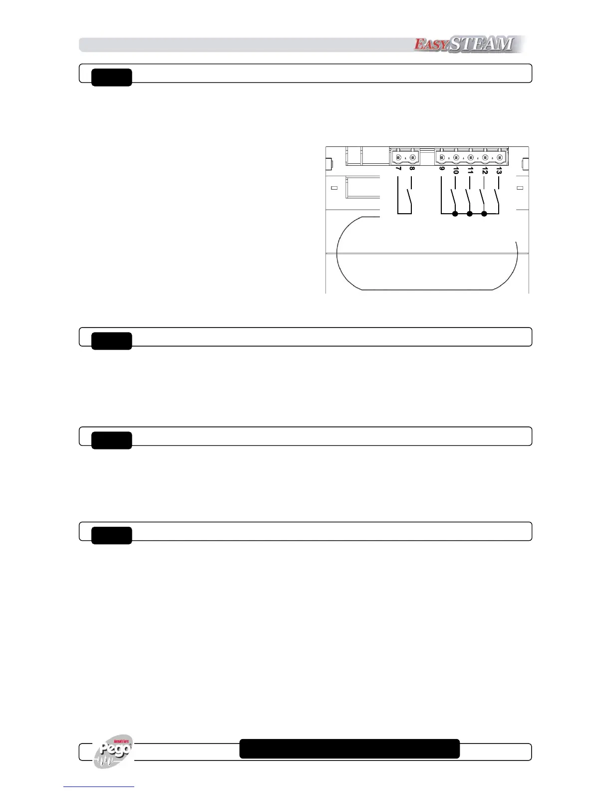
HUM2 BOARD DIGITAL OUTPUTS
Five relay are present on the humidifier electronics, two of which with configurable function:
Digital outputs Do1, Do2, Do3 Do5 are normally open contacts with a single common (clamp 9),
whereas output Do4 is independent and electrically insulated, in particular:
Output Do1 (clamps 9 and 10): Electrodes.
Output Do2 (clamps 9 and 11): water charge EV.
Output Do3 (clamps 9 and 12): Discharge pump.
Output Do5 (clamps 9 and 13): Configurable relay.
Output Do4 (clamps 7 and 8): Configurable relay.
By default this output is set as alarm
relay (second level variable dO4 = 1).
Relay capacity features:
Do1, Do2, Do3: 16(6)A 250Vac
Do4, Do5: 8(3)A 250Vac
In the ES series, outputs Do1, Do2, Do3 are already wired.
TA INPUTS FOR MEASURING CURRENT ABSORPTION
Two inputs from amperometric transformer are present on the humidifier electronics to measure the
current of the sunk-electrode:
TA1 (clamps 27 and 28): For connection of TA relating to cylinder N.1
TA2 (clamps 29 and 30): For connection of TA relating to cylinder N.2
BOARD POWER SUPPLY
The humidifier electronics requires a 230Vac 50/60Hz + -10% power supply and has a maximum
consumption of 5VA (electronic part only).
Power supply (clamps 2 and 3): 230Vac 50/60Hz power supply.
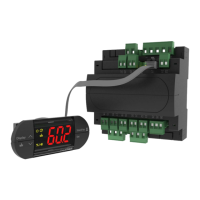
NANO EASYSTEAM DISPLAY FOR MASTERHUM2 BOARD
The MasterHUM2 electronics is the core of the humidifier to which a NANO EasySTEAM display
can be coupled, enabling the displaying of the machine status, the programming and configuration
of the parameters. Connection between display and Master happens by means of a cable with 8-
poles cross-connection RJ45 telephone connector (supplied with display) to be inserted in the two
J1 references.
The coupled use of Master and display is the most complete and recommended method but not the
only possible one; once configured, the MasterHUM2 electronics does not require the presence of
display and can be used independently. It is also provided with status LED (see chapter 3.2) and
switch (jumper) for the manual discharging of the cylinder (see chapter 2.5). In this single mode,
the alarms are reset by disconnecting power supply to the board.

 Loading...