Use of controls and adjustments
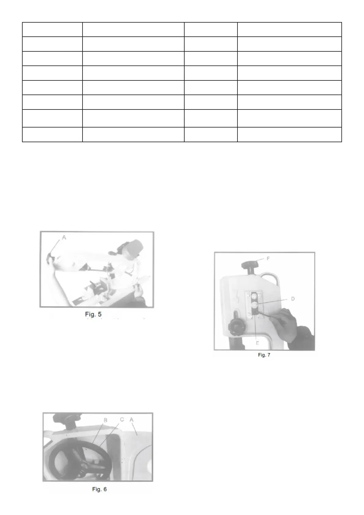
ADJUST TENSION OF BLADE
1. Disconnect the machine from the power
source.
2. Turn the handwheel on the tension (A)
clockwise to increase or counterclockwise
to decrease the tension of the blade. Correct
tension is only obtained when the blade is
suciently tight so that no slippage occurs
between the blade and the wheels. Fig.5
3. Release the voltage when the machine is not in
use.
Adjust control of blade
1. Place the saw arm in the opening position and
open the wheel cover (A). Fig.6.
2. Switch on the bandsaw. The blade is correctly
guided when the back of the blade (B) Fig.6,
only touches the edge of the wheel ange (C).
The back of the blade should not be against the
ange.
3. If an adjustment is required, the blade guide
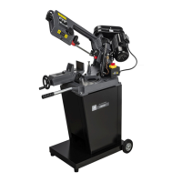
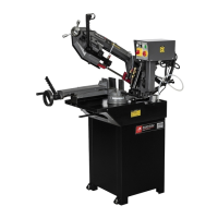
Product Description Product Description
1 Voltage adjustment, saw blade 2 Cutting angle locking lever
3 Adjustable blade guide 4 Adjustment, lowering speed
5 ON power button 6 Lowering cylinder
7 OFF button 8 Emergency Stop
9 Stop 10 Vice
11 Extendable handle for move-
ment
12 Drive belt protection / drive belt
housing
13 Protractor 14 Tension adjustment drive belt
bearing (E) Fig. 7 (two of which are shown)
must be free from the blade.
4. Loosen the screw (D) Fig.7.
5. With the metal band saw running, adjust the
screw (E) until the blade steers correctly. To
ensure that the tension of the blade is
maintained, turn the knob to the tension of the
blade (F). The blade steers correctly when the
back of the saw blade only touches the ange
on the wheel.
6. Tighten the screw (D) Fig. 7, when the
adjustment is complete.
7. IMPORTANT: IT IS POSSIBLE TO OVERTIGHTEN
THE ADJUSTMENT SCREW (S) FIG. 7, and
cause the blade to misalign. If this happens,
loosen the adjusting screw (E) several turns but
do not remove it from the threaded hole and
loosen the screw (D). Turn the screw (D)
clockwise until it stops but do not tighten. Then
turn the adjusting screw (E) clockwise until
it bottoms out. Switch on the machine and
turn the adjusting screw (E) clockwise a small
amount at a time until the blade tracks
correctly and tighten the screw (D) Fig. 7. When
the blade tracks correctly, make sure you set
the blade guide bearings and support bearings.
 Loading...