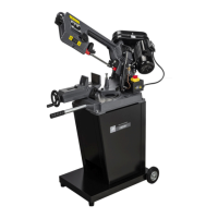
Adjust feed rate
1. Disconnect the machine from the power
source.
2. There is an adjustable hydraulic cylinder (A)
Fig. 12, which is connected to the saw arm
which regulates the speed at which the blade is
lowered towards the workpiece.
3. There is a rotary valve (B) Fig. 12, on top of the
hydraulic cylinder which is preset at the
factory. This rotary valve allows the pressure
to be relieved if for some reason the saw arm
should be pressed down. DO NOT attempt to
adjust the rotary valve setting.
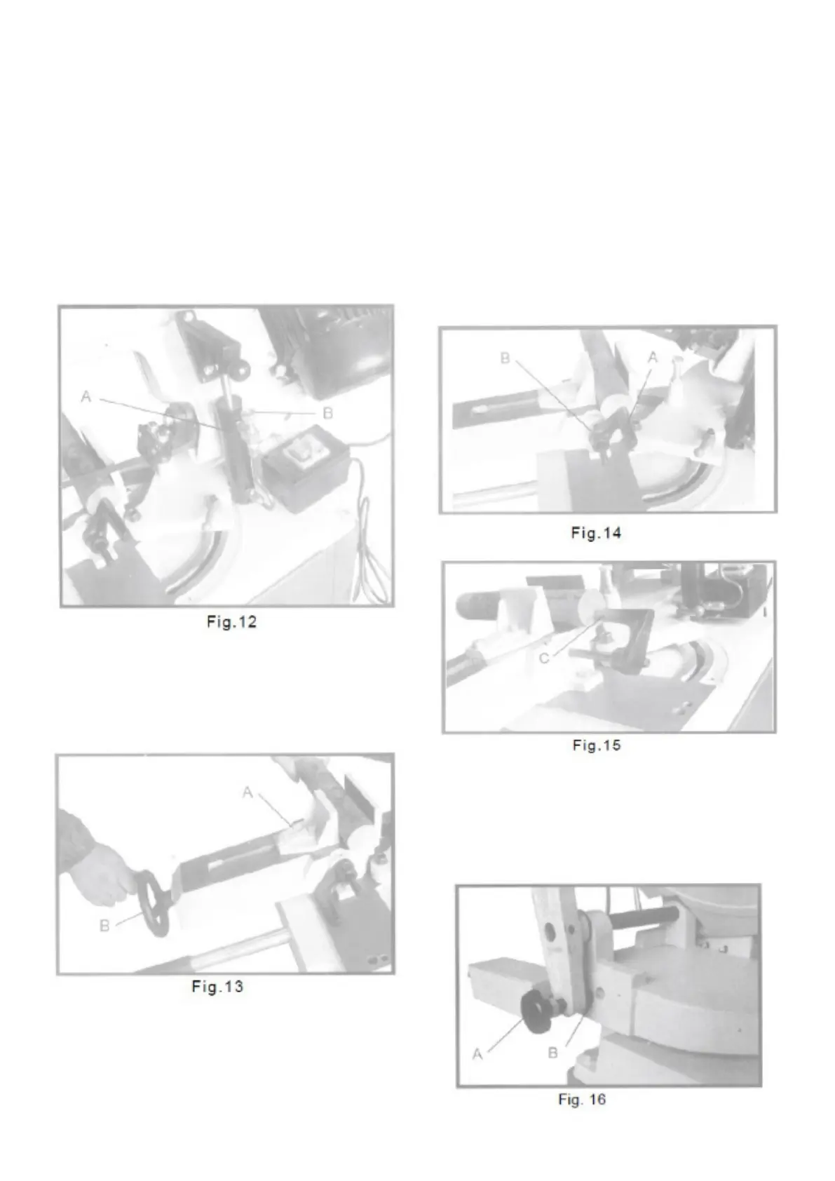
To use and adjust the anvil
The workpiece (A) is placed between the screw
jaws with the required amount to be sawn off past
the blade, as shown in Fig. 13. Turn the handwheel
(B) to tighten the workpiece in the anvil.
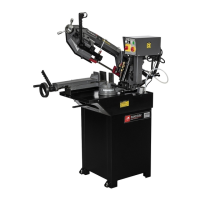
Adjustment of the stop
The stop is used when more than one piece is to
be sawn off in the same length. Position the stop
block (A) Fig. 14, to the desired distance from the
blade. It is good to have the workpiece touching the
stop at the bottom of the work, as shown. The stop
can be placed in or out by loosening the adjusting
screw (B) and moving the stop accordingly. When
not using the stop, rotate the stop under the table
surface.
For cuts when the work does not extend beyond
the table, the stop (C) Fig. 15 can be turned around,
as shown, to contact the workpiece.
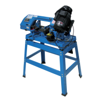
Positioning button
A position button (A) Fig. 16 for the arm, delivered
on the back of the base and placed in one of the
three holes (B) depending on the size of the
workpiece.