Calibration Procedure
Follow the steps below to calibrate the sensor.
1.
Make sure the sensor is clear of any toxic gas.
2. Remove the rain / splash guard if attached.
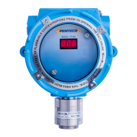
3. Place the magnetic tool against the cover at 8 o’clock position to activate the
magnetic switch as shown in figure 7
3. Place and hold the magnet until LED display on the front panel starts flashing
CAL. Move the magnet away from the cover.
4. While the display is flashing CAL the sensor is making its initial adjustments. It
may take 5 to 10 seconds. (Note: Do not apply calibration gas yet)
5. Once the initial adjustments are made the sensor will display the concentration
of the calibration gas to be applied. To match the displayed cal-gas reading to
the calibration gas bottle being used simply place and hold the magnet to the
cover at 8 o’clock position until the display reads the desired cal-gas value. The
calibration gas use can be anywhere between 5 to full scale range of the sensor.
Typically the calibration is performed at mid scale. For example, the sensor with
the detection range of 100 ppm the typical calibration gas should be 50 ppm. The
selected calibration gas value will be stored in the non-volatile memory and
remains unchanged until modified.
6. The microprocessor waits 60 seconds for the user to apply the calibration gas
while flashing the display approximately twice every second. Attach the
calibration adapter to the sensor head assembly and turn the gas on. When the
flow of the gas is detected by the sensor the display flashing rate will slow down
to once every second. If no gas is detected within 60 seconds the sensor aborts
calibration and will display E-3 error code “Calibration Time Out” for few
seconds before returning to normal operation..
7.
Apply the calibration gas for about one and a half (1 ½) minute.
8. After minute and a half the sensor will display Adj for 5 to 15 seconds while
making adjustments and recording the calibration data into memory. When
completed the display will starts flashing rapidly. At this time remove the
calibration gas and allow the sensor to clear. Do not remove the calibration
gas while Adj is being displayed. Remove the gas only when the adjustment is
completed and the display is rapidly flashing with calibration gas value.
**** For Oxygen Depletion sensor follow the procedure in next section. *******
PT295 Series Toxic Sensor Rev 5.1
20