ADJUST ALARM SETPOINTS
PT295 has a fully programmable relay for alarms. The alarm level can be set
anywhere between 0 and the full scale range of the sensor. Also they can be
configured as Latching or non-latching. The relay have Form “C” type contacts.
Setting alarm level or setpoint:
Alarm set point is set first and then relay is set for latching or non-latching. The
alarm configure mode is initiated by activating the magnetic switch on the right side
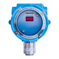
of the transmitter board. Refer to figure 9 for the position of the alarm
configuration switch
1. A magnetic switch for alarm configuration is located on the transmitter board at
4 o’clock position. Place and hold the magnetic tool at this position on the cover
of the junction box until the display starts flashing “ALr”. After few seconds the
current alarm set point will be displayed.
2. To change the current alarm level continue to hold the magnet. The alarm level
is incremented by 1. Move the magnet away once the desired alarm level is
displayed. Note: The alarm set point rolls over to 00 after the full scale range of
the sensor.
3. Wait for 10 seconds. The unit will display latching or non-latching state of the
low alarm ( “nL” non-latching, “L” latching). Hold the magnet to the
cover and display will toggle between “nL” and “L”. Select the desired latching
or non-latching alarm and move the magnet away.
4. The alarm is now configured.
Once alarm has been configured the sensor will return to normal operation. The
alarm configuration is saved in non-volatile memory and is not lost upon power
down.
For oxygen the alarm is activated on the falling edge. For example if the alarm level
is set at 18 %, the relay will be energized if the oxygen level is at or falls below 18%
PT295 Series Toxic Sensor Rev 5.1
26