Do you have a question about the PEMTECH PT750 Series W and is the answer not in the manual?
The PEMTECH PT750 Series Wireless Annunciator is a sophisticated gas detection system designed to monitor both fixed and wireless gas detection control panels. It serves as a central display unit, providing continuous gas readings and diagnostic messages from various detectors across a main rig and a rig camp. This system is engineered for ease of installation and operation, offering a comprehensive overview of gas levels and alarm conditions in critical industrial environments.
The primary function of the PT750 Series Wireless Annunciator is to act as a remote monitoring and control interface for gas detection systems. It communicates wirelessly with both the PT920 series Fixed control panel and the PT2008 Wireless Controller, consolidating data from multiple gas detectors into a single, user-friendly display. This allows rig managers and other personnel to quickly assess gas levels, identify potential hazards, and respond to alarms from a centralized location, typically the rig manager's office.
The system utilizes RS-485 wireless transmitters to establish communication between the annunciator and the control panels. These transmitters are installed on both the fixed and wireless control panels, converting their data into a wireless signal that the annunciator can receive. The annunciator itself features a wireless radio module housed within its enclosure, enabling seamless wireless communication.
A key aspect of its functionality is the ability to display real-time gas readings from all connected detectors. The data on the screen is updated frequently, typically every 2 to 3 seconds, ensuring that users have the most current information available. Each data block for a sensor provides not only the gas reading but also any relevant diagnostic or trouble messages, offering a complete picture of the detector's status.
The PT750 also incorporates alarm management features. When a sensor detects gas levels exceeding predefined thresholds, the system triggers an alarm condition. This is visually indicated by the sensor data reading flashing in red on the display, and bold alarm messages flashing on a status bar at the bottom of the screen. This immediate visual feedback ensures that personnel are alerted to hazardous conditions promptly.
Furthermore, the system includes an alarm test feature, which is crucial for functional testing and emergency preparedness drills. This allows users to simulate alarm conditions for H2S and LEL, enabling them to check the readiness of personnel and the system's response mechanisms. The alarm test can be activated for both low and high alarm levels, providing a thorough testing capability.
The annunciator also offers an alarm reset function. When the RESET button is pressed, the annunciator sends a command to the control panels to deactivate the alarms. If the gas condition has cleared, this action will also clear any flashing sensor location tags, indicating that the system has returned to a normal state. However, if high gas conditions persist, the control panel will reactivate the alarms, ensuring continuous safety monitoring.
Another important feature is the alarm bypass function. Pressing the Alarm Bypass button sends a command to the control panel to enter a bypass mode. For the fixed control panel, this is a soft bypass that lasts for 30 minutes, after which all control modules on the fixed system and wireless controller automatically return to normal mode. This feature can be useful for maintenance or specific operational procedures where temporary alarm suppression is required without compromising overall safety for extended periods.
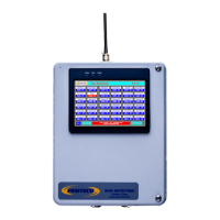
The PT750 Series Wireless Annunciator is designed with user convenience in mind, featuring a color touch screen display that provides an intuitive interface for monitoring and configuration.
The annunciator's touch screen displays continuous gas readings from all connected detectors. For standard units, up to 16 detectors can be displayed on a 4.5-inch screen, while larger screens are available for systems with more than 16 channels. This allows for a comprehensive overview of gas levels across the entire monitored area. The normal operation screen presents data in an organized manner, with each detector having its own data block. These blocks show the gas type (e.g., H2S, LEL) and the current reading. In alarm conditions, the display provides clear visual cues. Sensor data readings flash in red, and a prominent alarm message flashes on the status bar, ensuring immediate attention from operators. The system also displays various diagnostic and trouble messages, such as "FAULT," "Calib Mode," "Comm Err," and "Low Battery Signal" (for battery-operated wireless gas detectors), providing detailed insights into the status and health of individual detectors and communication links.
The annunciator offers a straightforward system configuration process, primarily focused on assigning sensor location tags and enabling/disabling channels. Upon power-up, a system information screen is displayed for a few seconds, showing details like the product number and firmware revision, before transitioning to the normal data screen. Accessing the configuration menu is done by pressing the "MENU" button on the lower left corner of the display. From this menu, users can:
The PT750 Series Wireless Annunciator is designed with considerations for straightforward installation and minimal maintenance requirements, primarily focusing on ensuring reliable communication and accurate data display.
Overall, the PT750 Series Wireless Annunciator is designed to be a robust and user-friendly system, providing essential gas detection monitoring with features that support both operational efficiency and maintenance effectiveness in challenging industrial environments.
| Display Type | TFT LCD |
|---|---|
| Display Size | 7 inch |
| Resolution | 800 x 480 pixels |
| Touch Screen | Resistive |
| Power Supply | 24V DC |
| Category | Control Panel |
| Humidity | 10% to 90% (non-condensing) |
| Communication Ports | Ethernet |
| Certifications | CE, FCC |
| Storage Temperature | -20°C to 60°C |