Maintenance Instructions
MODEL: P-1/2-HP, P-3/4-HP, P-1, P-1 1/2, P-2
NOTE:
This manual covers several different configurations of P-Series pumps.
Be sure to select the appropriate model number for your pump.
DISASSEMBLY
1. Remove the four (4) snap ring screws. Now the snap ring can
be removed using a screwdriver or a pair of pliers.
2. Insert a 2 inch threaded pipe through the center hole at the end
of the housing to remove the head. Pull with a rocking motion to
remove. Head O-rings can easily be replaced.
3. Unscrew the fan cover screws and remove the fan cover and
drip shield. Place the screwdriver between fan blades and
unscrew the impeller nut using a
3
/4 inch open wrench in a
counterclockwise rotation. Impeller nut O-ring can be replaced.
4. With the pump in a vertical position, impeller up, place a screw-
driver through the discharge port wedging between the impeller
top and the housing. Carefully lift the impeller and remove. If
impeller does not remove easily, proceed to step 5.
5. Remove the four (4) motor bolts located beneath the motor
bracket. Motor and housing are now separated. Do not try to
remove shaft as this is an integral piece with the motor rotor.
Slinger and lip seal can be replaced. Using a rubber mallet hit
the pump bracket lightly, top side facing motor, until the impeller
and keyway pop loose.
ASSEMBLY
1. With the motor in a vertical position, shaft upwards, place hous-
ing over shaft, lining up motor bolt holes in the mounting bracket
with holes in the motor. Be sure the slinger is properly in place.
Screw the motor bolts into the holes beneath the mounting
bracket in a diagonal sequence.
Be sure motor screws are tight.
2. Insert the impeller into the housing until it bottoms out. Do not
hammer the impeller and sleeve down on the shaft. Line up the
keyway and insert key by lightly tapping it with a hammer. Screw
the impeller nut clockwise holding impeller. Be sure impeller nut
O-ring is properly in place. After handtight, turn with wrench 180
degrees,10-15 inch lbs. DO NOT OVERTIGHTEN.
3. Replace the fan cover and drip shield. Insert the fan cover
screws and tighten. Be sure fan is not rubbing against fan cover.
4. Place the pump upright resting on the motor. Look down into the
housing and, while rotating the impeller, check to see that the
impeller is centered. The impeller must not be touching the side
of the housing.
5. Wet head and head O-rings. Be sure head O-rings are properly
in place. Insert 2 inch threaded pipe into the head and replace
in housing. The threaded pipe should be tapped with a mallet,
pushing the head into the housing until the snap ring groove is
exposed. Remove pipe and replace snap ring. Line up through
holes in snap ring
with the threaded
holes in the
head by rotating
the snap ring
counterclockwise.
Insert and tighten
the four (4) snap
ring screws.
DISASSEMBLY
1. Remove the four (4) snap ring screws, being careful not to lose
the O-rings. Remove the snap ring using a screw driver or a
pair of pliers.
2. Insert the appropriate threaded pipe through the center hole
at the end of the housing to remove the head. Pull with a rock
ing motion to remove. Head O-ring can easily be replaced.
3. Take the plug out from the back of the fan cover or drip shield.
Remove impeller nut assembly using a 7/16” wrench. Insert a
screw driver in the slot of the motor shaft and unscrew the
impeller counterclockwise using ngers or the handle end of a
pair of pliers.
4. Remove the four (4) motor bolts located beneath the motor
bracket. Motor and housing are now separated. Do not try to
remove the shaft as this is an integral piece with the motor ro
tor. Slinger and lip seal can be replaced.
ASSEMBLY
1. With the motor in a vertical position, shaft upwards, place
housing over the shaft, lining up motor bolt holes in the
mounting bracket with holes in the motor. Be sure the slinger
is properly in place. Conduit box should be 180˚ from the
outlet. Screw the motor bolts into the holes beneath the
mounting bracket in a diagonal sequence. Be sure motor
screws are tight.
2. Insert the impeller into the housing. With one hand holding
a screwdriver in the slot of the motor shaft and the other hand
on the impeller, turn the impeller clockwise with ngers or the
hankle end of a pair of pliers until the impeller bottoms out.
3. Attach impeller nut assembly to shaft with impeller nut O-ring
using a 7/16” wrench.
4. Place the pump upright resting on the motor. Look down
into the housing and while rotating the impeller, check to
see that the impeller is centered.
The impeller must not be touching the side of the housing.
5. Replace plug in the back of the fan cover or drip shield. Wet
head and head O-ring. Be sure head O-ring is properly in
place. Insert the appropriate threaded pipe into head and
replace in housing. The threaded pipe should be tapped with
a mallet, pushing the head into the housing until the snap
ring grove is exposed. Remove pipe and replace snap
ring. Line up through holes in the snap ring with the threaded
holes in the head by rotating the snap rings counter cloclwise.
Insert and tighten the four (4) snap ring screws.
7-
1
/
2
”
7-
3
/
8
”
(ref)
3”
4-
1
/
2
”
5-
1
/
2
”
1”
3
/
8
”ø
15
/
16
”
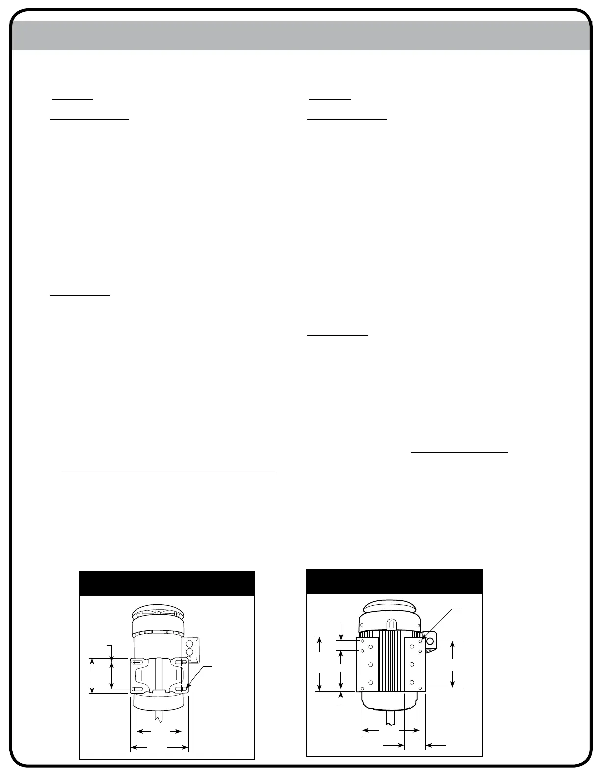
Mounting Diagram P3 - P7 1/2
Mounting Diagram P1/2 - P2
6.50”
4 SLOTS
.34 WIDE
4.88”
4.32”
3”
MODEL: P3, P5, P7-1/2
 Loading...