2 A19 Technical Bulletin
Models with adjustable differential and
ranges of 20/80F (-5/28C),
-30/50F (-35/10C) and -30/100F (-
35/40C) have a differential scale plate
showing increments of differential.
Other ranges have a scale plate with a
multiplier. For example when “MIN”
differential is 5F (2.8C) then x2 is 10F
(5.6C), x3 is 15F (8.3C), etc. The
controls are supplied with adjusting
lever at minimum differential stamped
on the control. To adjust move the lever
to the differential required.
Low cutout or high cutout stop supplied
on certain models (specified by the
equipment manufacturer).
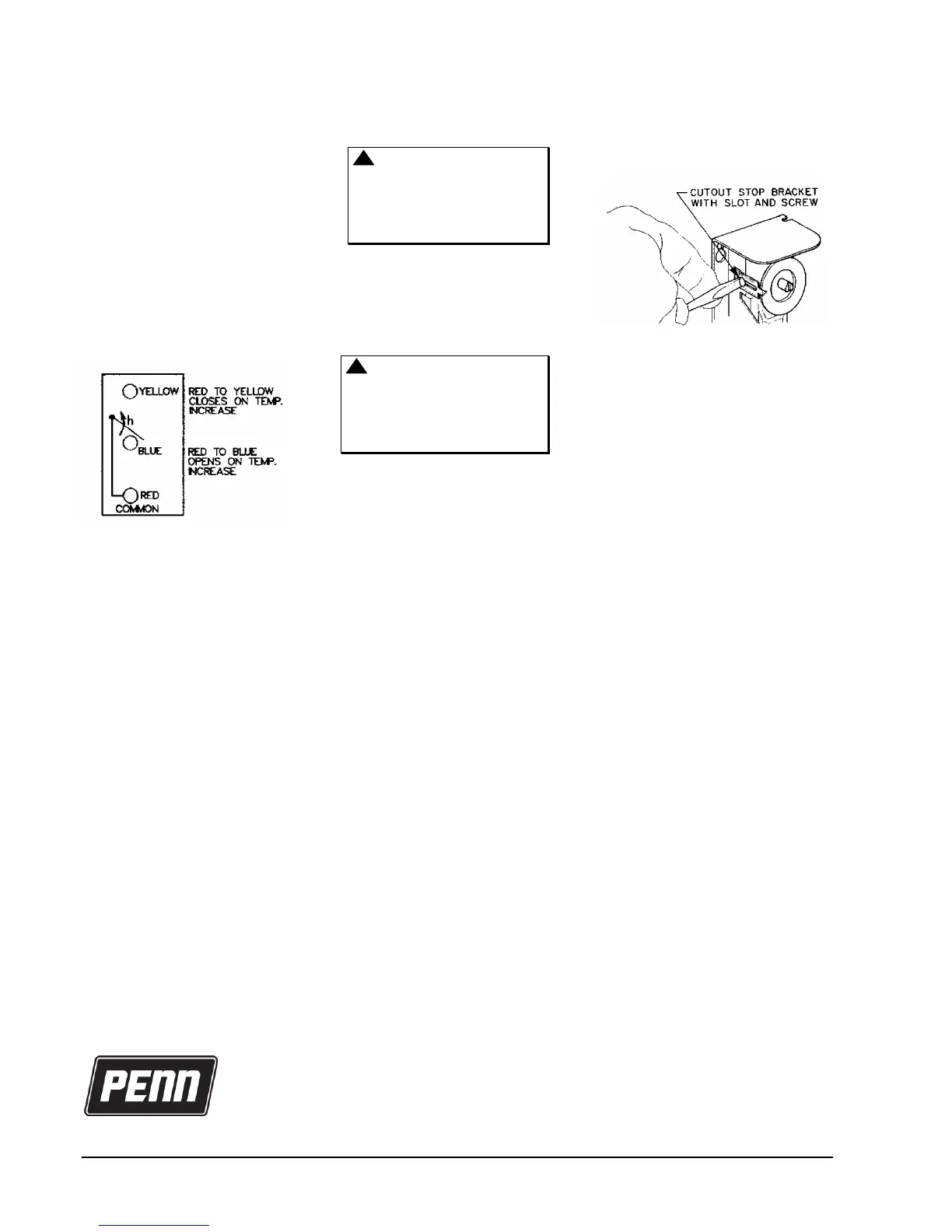
Fig. 4 -- Terminal arrangement of SPDT
models.
If high or low cutout stop adjustment is
required proceed as follows:
1. Set dial to temperature at which
stop is desired.
2. Remove cover of the control.
3. Loosen the cutout stop screw, slide
the screw to the front of the
temperature control against the
plastic step behind the dial and
tighten the screw. (See Fig. 5.)
Sometimes an exact stop setting is
not possible and stop must be set
to the closest stop corresponding
to dial setting required.
4. Replace cover.
Wiring
CAUTION: Disconnect power
supply before wiring
connections are made to
avoid possible electrical
shock or damage to
equipment.
All wiring should conform to the
National Electrical Code and local
codes. Single-pole, double-throw
models should be wired as shown in
Fig. 4. Use copper conductor only.
CAUTION: Use terminal
screws furnished
(8-32 1/4 in. binder head).
Substitution of other screws
may cause problems in
making proper connections.
Checkout Procedure
Before applying power, make sure
installation and wiring connections are
according to job specifications. After
the necessary mechanical adjustment
and electrical connections have been
made, an operational checkout is
recommended.
Adjust the control setpoint to put the
system in operation and observe at
least three complete operating cycles to
be sure that all components are
functioning correctly.
If the system fails to operate, recheck
the wiring and components.
Repairs and Replacement
Field repairs must not be made. For a
replacement control contact the nearest
Johnson Controls representative.
Fig. 5 -- All models have a screw type
cutout stop. The stop screw must be
loosened and moved to the stop setting
desired. Tighten screw after setting is
made.
European Single Point of Contact:
NA/SA Single Point of Contact:
APAC Single Point of Contact:
JOHNSON CONTROLS
WESTENDHOF 3
45143 ESSEN
GERMANY
JOHNSON CONTROLS
507 E MICHIGAN ST
MILWAUKEE WI 53202
USA
JOHNSON CONTROLS
C/O CONTROLS PRODUCT MANAGEMENT
NO. 22 BLOCK D NEW DISTRICT
WUXI JIANGSU PROVINCE 214142
CHINA
www.penncontrols.com
® Johnson Controls and PENN are registered trademarks of Johnson Controls in the
United States of America and/or other countries. All other trademarks used herein are the property
of their respective owners. © Copyright 2018 by Johnson Controls. All rights reserved.

 Loading...