Do you have a question about the PENNCO 15B II Series and is the answer not in the manual?
Defines DANGER, WARNING, CAUTION, and NOTICE symbols used throughout the manual.
Warns about fire, explosion, asphyxiation, and electrical shock hazards from improper installation.
Advises keeping the boiler area clear of combustibles and ensuring proper ventilation.
Outlines responsibilities for owners and installers, including qualified service and leaving instructions.
Presents a table detailing model numbers, input/output capacities, AFUE, and water content.
Provides critical notes on installation, electrical service, and altitude derating for optimal performance.
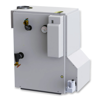
Details the essential components that come standard with the boiler.
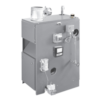
Illustrates the physical dimensions of the boiler with labeled points A through F.
Provides a detailed table of dimensions for each model, including gas inlet and tapping sizes.
Highlights severe risks associated with improper installation, including fire and personal injury.
Details adherence to codes like National Fuel Gas Code, ANSI Z223.1/NFPA 54, and CAN/CSA B149.1.
Specifies required clearances from the boiler to combustible materials for safe operation.
Mandates installation on non-combustible floors only, with specific warnings about carpeting.
Outlines methods for providing combustion and ventilation air as per codes like NFGC and CAN/CSA B149.1.
Details requirements for mechanical air supply systems, including interlocks and minimum air flow rates.
Explains calculations for minimum room volume and air infiltration rates for indoor air supply.
Describes methods for providing air supply directly from outdoors or through combined indoor/outdoor air systems.
Details critical safety requirements for installing the discharge line from the safety relief valve.
Lists specific criteria for the discharge line material, connection, support, and termination.
Provides guidelines for general hydronic piping installation, support, and adherence to codes.
Addresses specific installation scenarios like freezing, refrigeration, and air handling units.
Details the boiler's pressure rating, safety relief valve, and required temperature-pressure gauge specifications.
Explains the function and typical uses of bypass piping for system temperature control and protection.
Highlights severe risks from improper venting, including fire and carbon monoxide poisoning.
Prohibits connecting the boiler to any mechanical draft system operating under positive pressure.
Specifies rules for vent pipe slope, support, and connection to the chimney, including material and clearance requirements.
Outlines steps for safely removing a boiler from a common venting system without affecting other appliances.
Describes how to inspect the venting system for blockages, leaks, and deficiencies after boiler removal.
Details procedures for testing the venting system's performance after modifications, including sealing openings and running appliances.
Advises on re-sizing common venting systems according to National Fuel Gas Code standards after appliance removal.
Provides a step-by-step guide for physically installing the vent damper onto the boiler's vent outlet.
Specifies acceptable damper locations, clearance requirements, and operational positioning during main burner operation.
Outlines critical safety steps to take if a gas smell is detected, including avoiding ignition sources and contacting the supplier.
Covers piping materials, support, shutoff valves, and sediment traps according to relevant codes.
Presents tables for gas pressure requirements and pipe capacity based on length and size.
Details the process for pressure testing the gas piping and checking for leaks using acceptable methods.
Emphasizes turning off power at the service panel before any electrical work to prevent serious injury or death.
Instructs to bond the boiler to ground according to NEC/CEC and local codes for electrical safety.
Provides specific instructions for installing the thermostat in an optimal location, avoiding drafts and heat sources.
Displays the wiring diagram for the integrated high limit and electronic ignition control system.
Alerts users about the dangers of modifying or substituting factory-supplied electrical components.
Explains the different types of wiring lines and their voltage designations as depicted in the diagram.
Warns of severe hazards including fire and explosion if lighting procedures are not followed precisely.
Instructs to verify water levels, system venting, and thermostat settings before attempting to light the pilot.
Provides a step-by-step guide for safely lighting the pilot and starting the burner using the intermittent pilot system.
Details the correct method for shutting off the gas supply to the appliance for safety or servicing.
Explains how the thermostat initiates the heating cycle, activating the circulator and burner as needed.
Describes how high limit controls and safety switches (blocked vent, rollout) shut down the burner to prevent hazardous conditions.
Recommends professional checks for soot, scale, burners, and gas input rate for efficient operation.
Emphasizes the critical need to label wires before disconnection to avoid dangerous wiring errors during maintenance.
Outlines checks required after service, including water filling, air venting, and leak inspection.
Details procedures for inspecting the vent pipe and flue passageways for obstructions and damage.
Provides a step-by-step guide for cleaning the boiler's flue passageways, including burner removal and reassembly.
Guides visual inspection of burner and pilot flames for proper appearance, color, and envelopment of the electrode.
Explains how to adjust the pilot flame using the control knob and the importance of replacing the cover screw.
Reinforces keeping the boiler area clear of combustibles and ensuring adequate airflow for proper operation.
Recommends employing a qualified service agency for annual inspections and maintenance to ensure safe operation.
Details how to adjust the gas input rate by modifying the pressure regulator screw and checking manifold pressure.
Explains when to change burner orifices and notes that primary air adjustment is not standard.
Emphasizes testing the ignition system safety shutoff device after placing the boiler into operation.
Describes procedures for testing the intermittent pilot and the high limit control functionality.
Provides critical warnings and guidelines for the environment around the control module, including moisture and chemical avoidance.
Details how to connect the module's wiring harness, circulator, and thermostat using proper connectors.
Explains how to enter adjustment mode and modify parameters like setpoint (SP) and differential (Df).
Describes how to view operational status, parameters, and error codes on the control module's display.
Explains how the control module monitors temperature and thermostat calls to manage burner and circulator operation.
Lists and defines various state codes used by the control module to indicate system status and operations.
Describes how the high limit controller manages boiler temperature, including lockout conditions and manual reset.
Provides a guide for troubleshooting, including checking installation, wiring, and using service agents for repairs.
Introduces the diagnostic capability of the control module for identifying and resolving error conditions.
Lists specific error codes, their definitions, and consequences, aiding in diagnosing faults.
Details checks for the ignition cable, including its condition, connections, and continuity.
Explains the importance of proper grounding for the ignition system and how to verify its integrity.
Outlines steps to check the spark ignition circuit, including electrical safety precautions and listening for sparking.
Details procedures for verifying pilot ignition, main burner lightoff, and flame current, including visual checks.
Illustrates different pilot flame appearances and their corresponding causes, aiding in diagnosis.
Explains the boiler's feature that reduces water temperature to save energy as the heating load decreases.
Lists the specific conditions under which the energy saving feature's override function can be used.