switch low the brown magnet
lead.
8. The mirror mechanically releases
the shutter. As the first curtain
runs, it opens the timing switch in
the shutter block. ICI now starts
timing the exposure. To end the
exposure. IC'l commands IC'2 to
shut off the shutter magnet. IC2
turns off the shutter transistor.
The brown magnet lead switches
high, and the shutter magnet
releases the second curtain.
9. As you cock the shutter for the
next exposure, the wind-
completion switch closes. The
wind-completion switch clears the
counters in ICI and inhibits the
shutter release. With the shutter
fully cocked, the wind-completion
switch opens to enable the
shutter-release signal.
DISASSEMBLY HIGHLIGHTS
Settings for disassembly: main switch
off. speed knob on flash setting (100)
Locations of left-hand threads: wind-
lever screw. Fig. I
Sequence:
1 bottom cover (3 screws) —
rewind button and batteries loose
2. top cover
- wind-lever cover (1 screw,
underside)
- wind lever (left-hand screw)
Note: The early style wind-lever screw
has spanner notches. The current style.
Fig. 4. is a crosspoint screw. The
wind-lever screw has locking agent on
the threads. Use acetone or the heat
from a soldering iron to soften the
locking agent.
- top-cover nut around wind shaft
- rewind knob (screw at lop) - —
rewind shall loose
- 5 top-cover screws (the 2 screws at
the front of the camera have long
shoulders)
- lift the top cover and unsolder the
black wire from PC board TI00 and
the gray wire from the shutter-speed
PC board. Fig. 21.
3. remove handgrip leather
4. remove handgrip (crosspoint
screw and large minus-head plug)
5. remove right and left front leather
6. unsolder 1 I wires from top of
camera. Fig. 21
- 4 shutter-block wires (white,
red. and brown from PC board
T100. gray from shutter-speed PC
board)
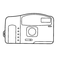
2ND GEAR C31
FIGURE 12
- 5 DX-block wires from PC
board T100 (pink, green, yellow,
brown, purple)
- wind-eompletion-swilch wire
from PC board T100 (orange)
- battery-box wire from PC hoard
T100 (red)
7. pull red, white, and brown
shutter-block wires to wind-lever
end of camera (the wires pass to
the front of the pentaprism)
8. remove screws holding shutter-
speed PC board (4 screws in early
models. 2 screws in later models)
9. remove 2 screws holding main
switch
10. cock shutter
11. remove 2 upper mirror-box
screws (I on either side of
eyelens)
12. remove 4 front-plate screws
13. lift out fronl-plaie/mirror-box
assembly
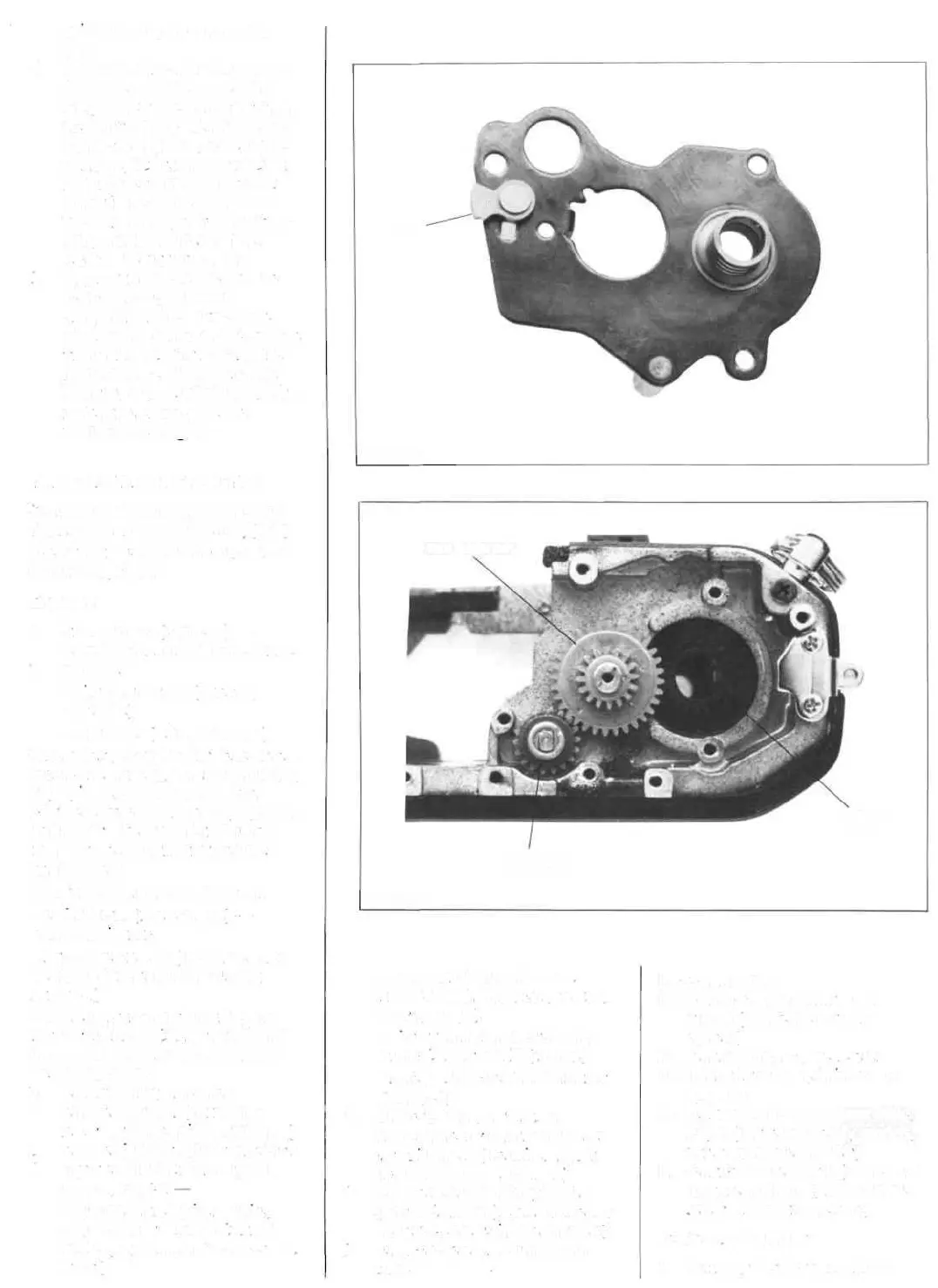
14. remove shutter-speed base plate.
Fig. 7 (3 screws in early models.
2 screws in later models)
15. remove shutter block (2 screws at
top of curtain unit. 1 black zinc
screw at back of aperture)
Reassembly highlights:
1. Before you replace the mirror
PAWL
FIGURE 11
SPROCKET
GEAR C33
SPOOL
GEAR