1.
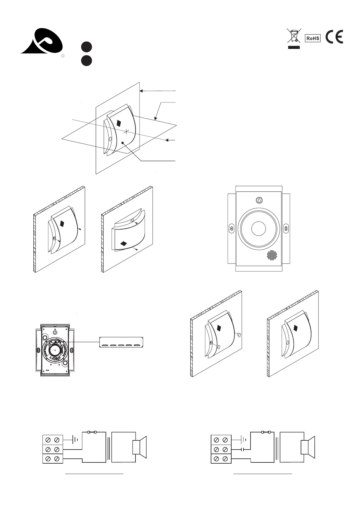
2.reference axis
3.horizontal plane
4.reference plane
loudspeaker enclosure
0359
13
PENTON
R
EN54-24:2008 TYPE A 0359-CPD-0151
PBC6T/ENC INSTALLATION GUIDE
>
PBC6T/EN
>
P2
1
2
4
3
COM.
100V
Circuit Diagram
TPBC6 /EN
Thermal Fuse
COM.
100V
Circuit Diagram
PBC6T/ENC
Thermal Fuse
* with capacitor
*
3W
1.5W
0.75W
6W
0.25W
3W
1.5W
0.75W
6W
0.25W
4)With the cable in place the speaker can be screwed through the
mounting holes into position. Once in position the two mounting
hole caps can be put in place to hide the offending screw heads.
There is also provided a key hole mounting plate, as shown on the
drawing, this can only be used if the loudspeaker is wall mounted
and in a vertical position.
3)Cabling can now take place, connect the 100 volt line supply
to your required volume as shown on the circuit diagram.
1)On selecting the chosen position for the loudspeaker (it can be
mounted vertically or horizontally) use a spirit level to ensure that it
is level. Offer the speaker to the wall or ceiling and mark through
the mounting holes, as shown on the drawing to the right, the
position required for drilling.
0.25W 0.75W 1.5W 3W 6W
2)Drill 2 holes 210mm apart and then raw plug them.
Mounting
Hole
Key
Hole
Mounting
Hole
 Loading...