Do you have a question about the Pepperl+Fuchs ARS11-B2-IA24-1 and is the answer not in the manual?
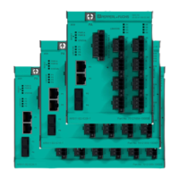
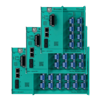
The Pepperl+Fuchs ARS*-B2-IA* Ethernet-APL Rail Field Switch is a ruggedized, managed switch designed to provide connectivity for Ethernet-APL and optionally PROFIBUS PA field devices to 100/1000-MBit/s industrial Ethernet networks. These switches are suitable for DIN rail or wall mounting and can be installed in explosion-hazardous Zone 2 environments.
The primary function of the ARS*-B2-IA* switch is to bridge Ethernet-APL and PROFIBUS PA field devices with industrial Ethernet networks. It features port diagnostics to facilitate fault finding within Ethernet-APL networks, offering valuable information for preventive maintenance of both the rail field switches and the connected network. An integrated web server allows for comprehensive management of the switch.
The spur connections of the rail field switches are designed to provide power to connected field devices. These spurs are intrinsically safe (Ex ia IIC) for Zone 1/0 and Zone 20 mounting, and are compatible with the Ethernet-APL port profile SPAA. The switch includes 2 RJ45 and 2 SFP Ethernet interfaces, enabling connection to industrial Ethernet networks such as PROFINET or EtherNet/IP. Two of the four ports can be configured for ring topology.
The device incorporates a sequential start-up management for its spurs. During start-up, spurs are activated one after another to minimize the initial high inrush current demand on the auxiliary power supply. This approach reduces stress on the power supply, thereby extending its expected useful lifetime. In the event of a spur short circuit, the spur current is quickly switched off. Once the short circuit is cleared, the spur current automatically returns. If multiple simultaneous short circuits occur, the current management system works to minimize the additional current demand on the auxiliary power supply.
The ARS*-B2-IA* switches are designed for flexible installation, supporting both DIN rail mounting (EN 50022) and wall mounting. For wall mounting, an accessory kit with two brackets is available; for the 8-spur version, only one bracket is needed. The switches are available in versions with either pluggable screw terminals or spring terminals, offering flexibility in wiring. Fiber optic small form-factor pluggable (SFP) transceivers are available as accessories, allowing for extended distance communication. These SFP transceivers are specifically approved by Pepperl+Fuchs for industrial use, including installation in explosion-hazardous areas, extended temperature ranges, and enhanced electromagnetic compatibility (EMC).
For installation in explosion-hazardous areas, specific precautions must be observed. The device must be mounted in a surrounding enclosure that complies with IEC/EN 60079-0 and is rated with at least IP54 according to IEC/EN 60529. The enclosure must also have an EU declaration of conformity according to the ATEX Directive for at least equipment protection level Gc (for gas atmospheres) or Dc (for dust atmospheres). Opening the enclosure while energized is only permitted if a potentially explosive atmosphere is absent or if the non-intrinsically safe circuits are protected by IP30.
Unused Ethernet ports P1-P4 must be equipped with protective covers (ACC-PC-45 for RJ45 ports and ACC-PC-SFP for SFP ports) to maintain the required degree of protection. Similarly, unused terminal connections for PWR A and PWR B on the 6-pole auxiliary power connector must be covered with isolated wire end ferrules, crimped to prevent exposure of conductive parts.
When using spurs in type of protection Ex ia, a clearance of 50 mm must be maintained between non-intrinsically safe circuits (e.g., Ethernet ports P1-P4) and the intrinsically safe spur terminals. Separation walls (ACC-ARS-SW) are provided to ensure this clearance.
The device requires a DC voltage supply of 20 V to 60 V (Un) that meets SELV or PELV requirements, not exceeding 60 V DC even under fault conditions. The cross-section of power cables must be chosen in accordance with the maximum fuse protection of the external circuit.
The device features a grounding terminal marked "PA" for equipotential bonding, requiring a conductor with a minimum cross-section of 4 mm². Cable shields of spur cables are capacitively coupled to the grounding terminal, and field device cable shields must be connected to local earth. Ethernet copper cables are directly connected to the grounding terminal via the RJ45 connector.
The ARS*-B2-IA* provides LEDs for status and diagnosis information for the rail field switch itself, Ethernet ports, and spur ports. These indicators help in troubleshooting and identifying operational issues. For example, PWR A/B LEDs indicate power availability, LNK/CHK P1-P4 LEDs show communication status and activity, and S1-Sn LEDs provide status for spur ports, including communication link establishment, activity, PROFIBUS PA communication, and overload conditions.
A reset button is available to reboot the rail field switch; it can be operated during normal operation, even in explosion-hazardous areas. Pushing the button for at least 5 seconds initiates a reboot. For more detailed diagnosis information, users can refer to the software manual or access the web server and asset management tool.
When installing or removing SFP transceivers, it is crucial to ensure that power is removed to prevent explosion hazards from sparking. Additionally, electrostatic discharge (ESD) precautions must be observed, including wearing an antistatic wrist or ankle strap connected to an approved grounding source. Unused SFP transceiver slots should be covered with protective caps (ACC-PC-SFP) to prevent dust ingress and unintentional harm. Similarly, protective covers (ACC-PC-45) are available for RJ45 sockets.
| Housing material | Plastic |
|---|---|
| Shaft type | Solid |
| Shaft diameter | 6 mm |
| Signal type | SSI |
| Connection type | Cable |
| Cable length | 2 m |
| Protection degree | IP67 |
| Output type | SSI |
| Product Category | Rotary Encoder |
| Type | Absolute |
| Operating voltage | 10 ... 30 V DC |
| Output code | Binary |
| Operating temperature | -25°C to +70°C |