perco.com linkedin.com/mwlite/company/perco export@perco.com +7 (812) 247-04-64
Layout description
Item Description
А1 Master section (side of the section)
А2 Slave section (side of the section)
А3 RC-panel
А4* Turnstile power supply
А5* Device for sending FireAlarm command
А6*, А6.2* ACS controller
А7* WRC
А8* 12V DC siren
А9.1*, А9.2* Remote indication block
А10* Remote indicators PS
1, 2 DC connection cable
3, 4 CAN connection cable
5 Jumper wire in case there is no Fire Alarm device (A5). Installed by default.
* The equipment is not included in the standard delivery set
Operation
algorithm
The speed gate can operate from an RC-panel (included in the delivery set), WRC and ACS
controller.
Operation is performed by applying a low-level signal to Unlock A, Stop and Unlock B
contacts relative to the GND contact. The response to these signals depends on the control
mode selected by the Pulse switch.
Pulse control mode (Pulse switch in the ON position) is when a pulse is applied to the Unlock
A (B) input, the speed gate panels will automatically open for a single passage in the A (B)
direction. The waiting time for the passage being completed does not depend on the duration
of the control pulse and lasts 8 seconds. Sending impulse to the Stop input closes the panels
from any position, thus blocking the passage. Simultaneous sending of pulses to the Unlock A
(B) and Stop inputs places the turnstile in the "Free passage" mode in the selected direction.
It is recommended to use pulse mode when operating from an RC-panel or WRC. The orientation
of the RC-panel buttons can be changed by swapping the wires from the RC-panel that are
connected to the unlock A and Unlock B contacts, as well as Led A and Led B, respectively.
Potential control mode (Pulse switch in the OFF position) is when the control signal is applied
to the Unlock A (B) input, the glass panels slide away in the selected direction during the
entire holding signal time. Sending the control signal to the Stop input closes the sliding panels,
thereby blocking the passage, regardless of the signals at the Unlock A (B) inputs.
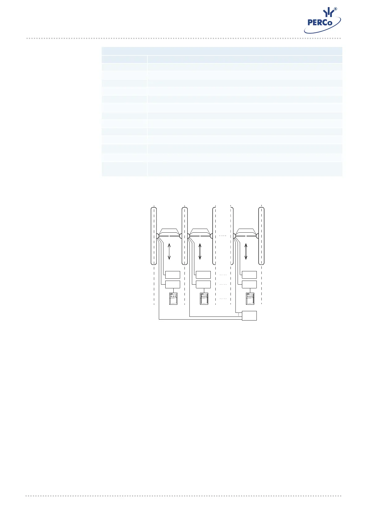
Connection of the ST-01 turnstile and STD-01 bidirectional sections to arrange a passage zone with several passage lanes
PS#1
FA
ACS# 1
DC
CAN
PS#2
ACS#2
RS#1 RS#2
MASTER
SLAVE
MASTER
SLAVE
DC
CAN
MASTER
SLAVE
DC
CAN
PS#’N’
ACS#’N’
RS#’N’
1 2 ‘N’
‘N’
1
2
ST-01 Speed gate
 Loading...