perco.com linkedin.com/mwlite/company/perco export@perco.com +7 (812) 247-04-64
Potential mode is recommended when operating from the ACS controller.
Regardless of the selected control mode, PASS A or PASS B signals are generated when passing
in one direction or the other. These signals can inform the ACS controller of the fact of passage.
Emergency opening of the passage lane is performed by removing a low-level signal from the
Fire Alarm contact relative to the GND contact.
The product also features an additional "Automatic opening in the selected direction" mode
(R1 switch in the ON position). This is a mode of free passage through the turnstile in one pre-
selected direction (selected by the R2 switch) with automatic opening and closing of the panels
during passage.
Training mode (R1 switch in the OFF position, and R2 switch on the ST-01.771 control board
in the ON position) allows manually adjusting the home (closed) position of the turnstile swing
panels.
Note
When operating the speed gate from the ACS controller, it is recommended to connect the
RC-panel to the ACS controller.
The maximum allowed cable length from the RC-panel (ACS controller) is 40 meters.
The maximum allowed cable length from the power supply depends on its cross section and
must be:
• for 1.5 mm
2
cable – 10 meters
• for 2.5 mm
2
cable – 20 meters
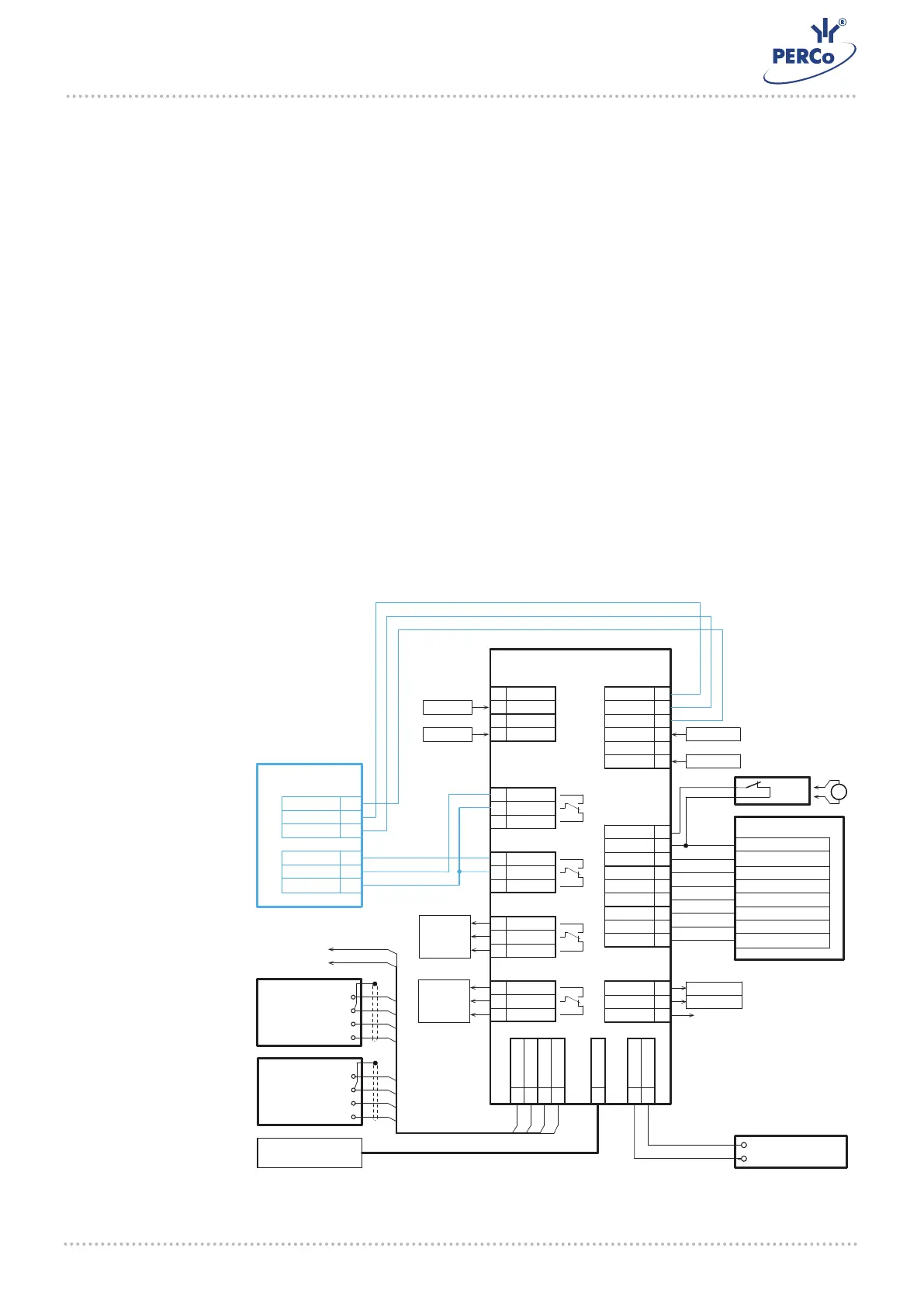
A layout example of the speed gate connection to the ACS controller
Example of
connection to the
ACS
CT/L-04.2
XT10
XT6
XT7
XT9
XT3
XT8
XT2
XT1
XT5
S1
XT4
ШС
OUT1
OUT2
OUT4
IN
RC
OUT ОC
RS-485
TCP / IP
+12V
ШС1+
OUT3
ШС1-
ШС2+
ШС2-
NO1
С1
NС1
NO2
С2
NС2
NO3
С3
NС3
NO4
С4
NС4
IN1
GND
IN2
IN3
GND
IN4
FA
GND
DUA
DUSt
DUB
LdA
LdSt
LdB
Buzz
OK2
OK1
+12V
+12V
GND
B
A
GND
+12V
B
A
GND
+12V
LAN
TCP / IP
PS
GND
+12V
1
2
3
4
1 2 3 4
FA
LEFT BUTTON
STOP BUTTON
RIGHT BUTTON
LEFT INDICATOR
STOP INDICATOR
RIGHT INDICATOR
BUZZER
OUTPUT 6
OUTPUT 5
INPUT 5
INPUT 6
1
+12V
3
4
RS-485 to AI01,
CL201.1, AU05
1 - jumper wire, installed when there is no FA device
1
2
3
4
Reader
1
INPUT 3
INPUT 4
OUTPUT 3
OUTPUT 4
1
2
3
1
2
3
1
2
3
1
2
3
1
2
3
1
2
3
1
2
1
2
1
2
1
2
1
2
1
2
3
1
2
3
1
2
3
1
2
3
B
A
GND
+12V
Reader
2
X3 «ACS»
6
5
7
2
1
4
COMMON
PASS B
PASS A
UNLOCK A
GND
UNLOCK B
ST-01
RC
WIGHT
BLUE
GREEN
BROWN
YELLOW
ORANGE
RED
BLACK
COMMONX2 «RC»
ST-01 Speed gate
 Loading...