4
Owner’s Guide PCC-100 & PCC-200
STEP 1
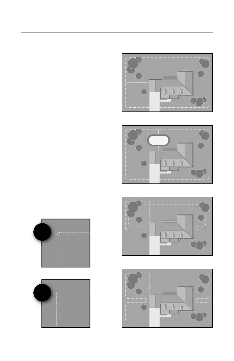
Planning your fence layout
• When designing your fence layout, it is
important to remember that your fence
boundary is one continuous loop of
wire, starting at your wall-mount trans-
mitter, forming a boundary loop around
your selected area and returning back
to the transmitter.
• You will need to allow room in your
plan for 8’ – 10’ of signal area from the
boundary wire.
• Do not run the boundary wire within 10’
parallel of utility lines. Utility lines can
create interference. Have utility lines
marked prior to fence wire installation.
• To maintain a consistent signal fi eld use
a gradual radius when running the wire
around corners, as illustrated. Avoid
hard 90 degree angles.
Entire Yard
Around Obstacles
Back Yard Only
Separate Front & Back
√
×