Perlick is committed to continuous improvement. Therefore, we reserve the right to change specications without prior notice
2
Form No.Z2278
Rev. 10.04.10
Parts List
• (3) Shelves per door (one may be used as a oor
rack)
• Shelf clips
Tools Required
• #2 Phillips Screwdriver
• 10” Cresent Wrench
• 9/16” Allen Wrench
• 5/16” and 3/8” Hex Socket
• Power Drill or Driver (for leg caster installation)
Plumbing
Condensate from the cooling coil is automatically
evaporated through a condensate pan located in the
condensing unit housing. Each unit is also equipped
with a oor drain located in the right rear corner of
the cabinet. The drain can be plumbed to an external
oor drain by connecting to the 3/4” NPT thread out
the side or the 1” NPS thread out the bottom. Both
drains ports come plugged from the factory and can
be removed if needed.
NOTE: Remote units require evaporator condensate
to be plumbed to an external drain.
Electrical
The cabinet must be connected to a separately
fused power source (see electrical specification
plate) and grounded in accordance with National
and Local Electrical Codes. Caution: Do not
attempt to operate the equipment on any other
power source than that listed on the Electrical
Specification plate.
Uncrating and Inspection
Remove all crating material before operating.
Carefully inspect cabinet for hidden damage. If
damage is discovered, file your claim immediately
with the transportation company. Perlick isnot
responsible for damage in transit.
Plumbing
Push the cabinet into place using rollers when
necessary. IMPORTANT: Proper air ow around the
condensing unit is necessary for ecient operation.
Never obstruct the air ow in and out of the
condensing unit.
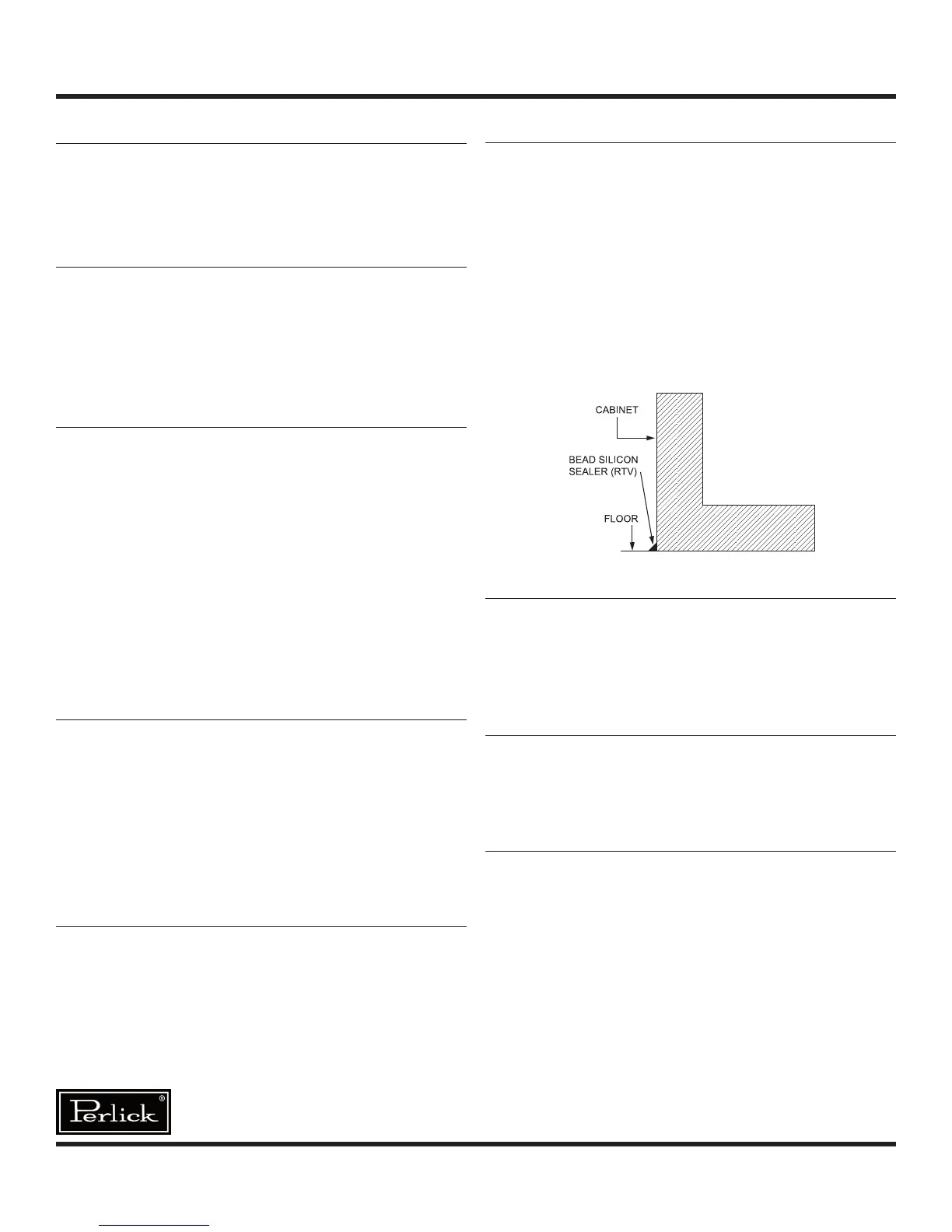
For sanitation purposes, it may be necessary to
seal the base of the cabinet to the oor. This can be
accomplished by laying a bead of silicone sealant
between the base of the cabinet and the oor as
shown by the gure below:
Leveling the Cabinet
When the cabinet is in place, check installation with
carpenter’s level. When level front to back and left
to right, accumulated water will drain out of the
cabinet evaporator drain.
Installing Casters or Legs (optional)
Attach casters or legs to cabinet bottom in holes
provided. Use the supplied 1/4”-20 x 3/4” hex head
self-tapping machine screws.
Installing Base Plate (optional)
Attach brackets to cabinet bottom in holes
provided. Attach base plate to brackets (see
separate instructions, provided with kit). When
returning cabinet to upright position, be careful not
to bend brackets.
WARNING! To avoid compressor damage, after
running cabinet in an upright position, let unit stand
for 24 hours before plugging in and running the unit.
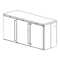
GENERAL INFORMATION – Custom Back Bar Cabinets