PERLICK RESIDENTIAL UNDERCOUNTER CUBELET ICE MAKER PRODUCT MANUAL
22 | perlick.com/residential
WATER SUPPLY AND DRAIN CONNECTIONS
WATER SUPPLY AND DRAIN CONNECTIONS
Water supply and drain connecons must
be installed in accordance with applicable naonal, state, and
local regulaons.
Normal operang water temperature must be
within 45°F to 90°F (7°C to 32°C). Operaon of the appliance,
for extended periods, outside of this normal temperature range
may aect appliance performance.
Water supply pressure must be a minimum of
7 PSIG and a maximum of 113 PSIG. If the pressure exceeds 113
PSIG, the use of a pressure reducing valve is required.
External lters, strainers, or soeners may be
required depending on water quality. Contact your local Perlick
Cered Service Representave or local Perlick distributor for
recommendaons.
Connect to potable water supply only. Do not
connect to a hot-water supply.
In areas where water damage is a concern,
install in a contained area with a oor drain.
WARNING
DANGER
!
WARNING
WARNING
WARNING
Water line installaon to the appliance is not
warranted by Perlick.
Water-hammer issues must be resolved
by a qualied plumber before installing the appliance. Water
hammer can cause appliance damage that may lead to water
leakage or ooding.
A minimum of 1/2” nominal ID hard pipe
or equivalent is required for the drain line. Installing a smaller
diameter drain line will reduce water ow and may lead to
water leakage or ooding.
If using the oponal drain pump (63802A),
test its operaon every me the appliance is cleaned and
sanized. If the oponal drain pump is not operang properly,
water could back up and overow, leading to costly water
damage.
WARNING
WARNING
WARNING
WARNING
WARNING
Water Supply Inlet Minimum Water Supply Line Size Drain Outlet Minimum Drain Line Size
1/2" Female Pipe Thread (FPT) 1/4" Nominal ID Copper
Water Tubing or Equivalent
1/2" Female Pipe Thread (FPT) 1/2" Nominal ID
Hard Pipe or Equivalent
A plumbing permit and services of a licensed plumber may be
required in some areas.
A water supply line shut-o valve and drain valve must be
installed.
Be sure there is sucient extra water supply line and drain line
for the appliance to be pulled out for service.
Drain line should not be piped directly to the sewer system
An air gap of a minimum of 2 vercal inches (5 cm) must be
between the end of the drain pipe from the appliance and the
oor drain.
For gravity drain installaon, drain must have 1/4” fall per foot
(2 cm per 1 m) on horizontal runs to get good ow. A vented
tee connecon is also required for proper ow. Extend the vent
at least 12” (30 cm) above the drain outlet. For oponal drain
pump installaon, refer to the instrucons included with the
pump.
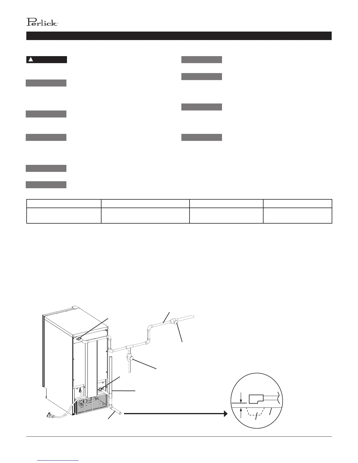
Fig. 23
Piping to approved drain. Leave a 2-inch (5-cm)
vercal air gap between the end of the pipe and
the drain.
2-inch (5-cm)
air gap
Floor
Drain
Shut-O Valve
Drain Valve
Water Supply Inlet
1/2" FPT
Drain Outlet
1/2" FPT
Vented Tee Connecon
Extend the vent at least 12" (30
cm) above the drain outlet.
Minimum 1/4" Nominal ID Copper Water Tubing or Equivalent
Minimum 1/2" Nominal ID Hard Pipe or
Equivalent
Be sure there is sucient extra water supply line
and drain line for the appliance to be pulled out
for service.
 Loading...