Refit the road wheel
beÍore
lowering
the car to the
ground,
adlust the
brakes as detailed
in
Section
10:2.
Reassembling lefthand
front brake :
1
Remove
the
wire from around the brake cylinder and
piston.
2 Position the brake shoes against the
brake
plate
and
secure
with
the
lateral
springs. The offset end
oÍ
the
brake shoes should be located in
the
same manner as
Íor the righthand
brake, r.e.
Towards the front
for the upper brake shoe.
Towards the rear for the lower brake
shoe.
3
Install both inner
springs, using the brake tool, in the
Íollowing manner:
Position
the springs
between
the brake
shoes and
the brake
plate
and engage
the small
hook
oÍ each
spring
in
the corresponding holes in the brake shoes.
Engage the tool, hook
'a',
in
the spring hook and
rotate tool
around the Íixed
point.
At the same time
pull
on
the tool
until
it is
possible
to engage the
spring
hook.
Remove the tool.
4
Install the outer springs. The larger hooks
oÍ the
inner
springs may be closed slightly after f itting if
necessary.
5
ReÍit
the brake
drum to the hub and adtust the
brakes.
Brake
shoe springs:
All the brake shoe inner return springs
are
identical
and
incorporate
26 turns.
The outer
return
springs
(see
item 2
oÍ
FIG
10:10),
are different for the left' and righthand
brakes.
The
spring
hook
position
on
the spring
difÍers, to
prevent
chafing
of
the
spring
wire against the brake cylinder
boot
(see
FIG 10 : 10).
10:4
Checking the brake
pedal
travel
1
Start
the engine and accelerate
two or
three
times
rn
succession to obtain the maximum vacuum in the
Hydrovac
unit.
2 Run the engine at idling
speed
and measure
the height
of the brake
pedal
from
the
Íloor.
3 Depress the brake
pedal
until the
vacuum is
gone
from
the
Hydrovac
unit. At this
point
the effort
required
to
depress
the
pedal
increases
suddenly.
4
Hold the
pedal
in the
depressed
position
and again
measuíe
the height
of the
pedal
from the floor.
5
The movement of the
pedal
can
now be
calculated,
and this should not exceed 60 mm
(approx.
2.4
i n ches) .
6 lf
the
pedal
movement is more than thls it is an
indication
that the brakes need adjusting. lf the
pedal
movement
is
still
excessive
aÍter adjusting the brakes
the
brake
system
should be bled.
10:5 Hydraulic equipment
The hydraulic equipment fitted to the Peugeot
404
includes
(after
1965), a Hydrovac vacuum controlled
power
brake
unit,
operated by the master cylinder.
The Hydrovac is
a sealed unit and no dismantling
is
permitted
or required, apart from changing
the
filter
element. The element must
be
replaced
with a new
item
as no cleaning
or
oiling is
permissible.
The Hydrovac unit
is
shown in FIG 10 : 1 1 .
P404
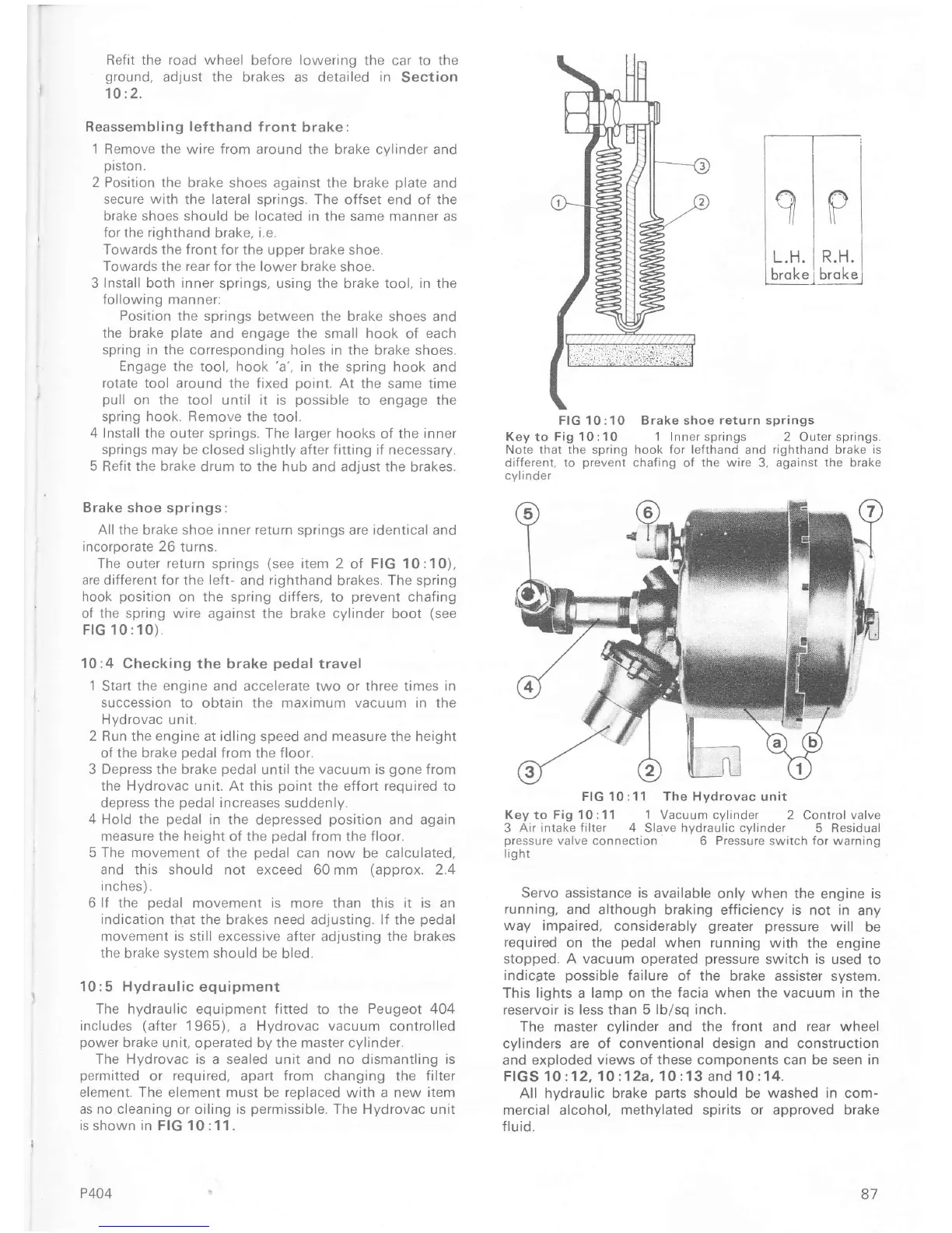
FIG
10:10 Brake shoe
return
springs
Key to Fig 10:10
1 Inner
springs 2 Outer springs.
Note that the spring hook
Íor
leÍthand and righthand brake
is
diÍJeÍent, to
prevent
chaÍing
of
the wire
3,
against the brake
cyilnoer
FIG 10:11
The Hydrovac
unit
Key
to Fig
10:11 1 Vacuum
cylinder 2 Control valve
3
Air intake filter
4 Slave hvdraulic cvlinder 5
Resiouar
pressure
valve connection
6 Pressure switch
for
warning
lig ht
Servo assistance is
available
only
when
the engine is
running,
and although braking efficiency is
not in
any
way
impaired,
considerably
greater pressure
will
be
required
on the
pedal
when
running with the
engine
stopped. A
vacuum
operated
pressure
switch
is
used to
indicate
possible
failure
of the brake assister system.
This lights a lamp on the
facia
when the vacuum in the
reservoir is less than 5
lb/sq inch.
The master cvlinder and the
front
and
rear
wheel
cylinders are
of conventional design and construction
and exploded
views oÍ these components can be seen in
FfGS 10:12,
1O:12a,1O:13
and
í0:14.
All hydraulic
brake
parts
should be washed in com-
mercial alcohol, methylated spirits or appÍoved brake
f lu id.
87

 Loading...


