GB
Worm gear screw jack SHE type1 and type2
High-performance screw jack HSE type1 and type2
T13.01.000.0000.0003
2019/04 Rev. Index E
Subject to technical modifications Design changes under reserve Sous réserve de modifications techniques !
15
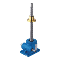
7.3 Pivot version
Version P Version Q
Version P or Q defines the position of the worm
shaft towards the swivel axis.
Display SHE (also deliverable as HSE)
No side forces due to alignment errors. Distortions increase power consumption and reduce the service life!
If necessary, install movable load support points or pivoting bearings.
Fasten screw jacks using only quality bolts and screws.
Secure bolts and screws.
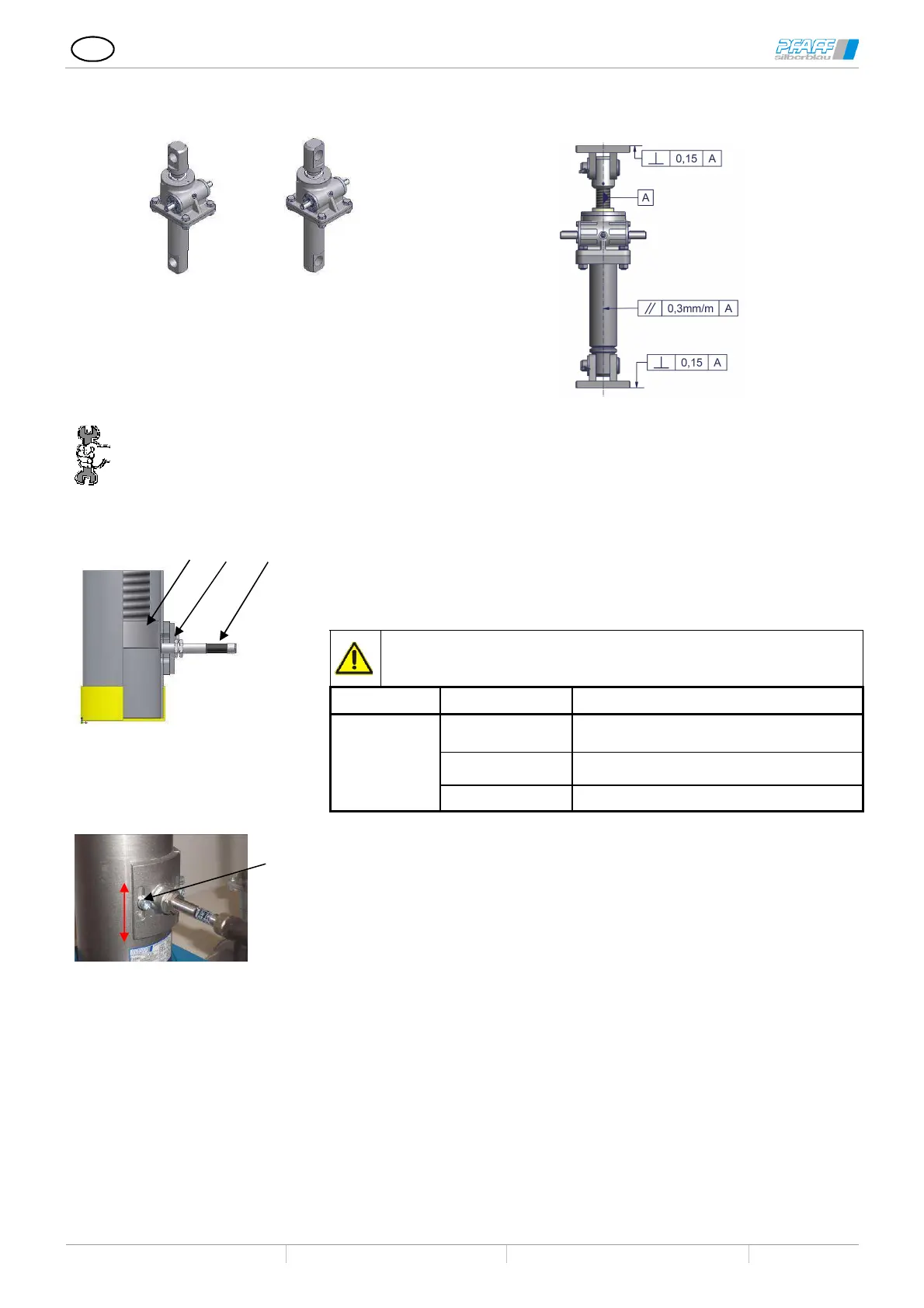
7.4 Assembly of the inductive limit switches
1 Switching cam
2 Counter nut
3 Inductive sensor
4 Sensor fittings
Run switch cam on sight
Screw in the displacement sensor until it is aligned with the inner diameter of
the tube wall thickness.
Secure the sensor emitter by tightening the hexagon nut and ensure that the
emitter does not turn or the position is otherwise changed.
If the sensor protrudes toward the interior, it will be destroyed.
Observe the maximum tightening torque!
Material Type Maximum tightening torque [Nm]
Metal
M 8 2,5
M 12 7
M 18 35
Adjusting the switch point:
Loosen screws (4).
Slide the holding plate up or down
Tighten screws. Observe the tightening torques!
1
3 2
 Loading...