Do you have a question about the Pfeiffer Vacuum QMG 700 HIQUAD and is the answer not in the manual?
| Type | Quadrupole Mass Spectrometer |
|---|---|
| Weight | Approx. 10 kg |
| Power Supply | 100-240 V AC, 50/60 Hz |
| Interface | RS-232 |
| Filament | Iridium |
| Detector | Secondary electron multiplier (SEM) |
| Resolution | Unit Resolution |
| Dimensions | 19" rack mountable |
| Mass Range | 1 to 512 amu |
Describes the product function and important safety information, based on current directives.
Identifies personnel performing activities like transportation, setup, usage, and maintenance.
Explains text conventions, pictographs, product stickers, and abbreviations used in the manual.
Lists registered trademarks associated with the product and its components.
Details risk levels (DANGER, WARNING, CAUTION) and information level (NOTICE) used in the document.
Provides safety instructions based on product life stages and identifies risks during installation, operation, and maintenance.
Outlines general safety precautions for handling the product, duty to inform, and risks from modifications.
Specifies that the QMG 700 is for gas analysis in high vacuum and must be operated per instructions.
Lists examples of improper use that invalidate warranty and liability claims.
Defines Pfeiffer Vacuum's and the operator's responsibilities regarding product use and modifications.
Details owner requirements for safe operation, including technical state and personnel qualification.
Specifies qualification requirements for mechanical and electrotechnical work and advanced training.
Lists requirements for operators, including observing documents, limits of use, and contacting service.
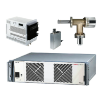
Describes the main components of the QMG 700 system, including control unit, HF generator, and analyzer.
Details the QMS 700 control unit, comprising system chassis SC 700 and QC 700 board.
Explains the function of the HF generator QMH 40x in generating high-frequency voltage for mass separation.
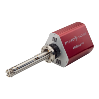
Describes the QMA 4x0 analyzer, including its components and ion collector types.
Details the EP 422 pre-amplifier for amplifying ion signals and its properties.
Explains the CP 400 pre-amplifier containing pulse decoupling, amplifier, and discriminator.
Provides connection diagrams and pin assignments for various modules and interfaces.
Describes system wiring configurations for different operating modes.
Instructs users to use rating plate data for product identification when communicating with Pfeiffer Vacuum.
Lists the items included in the QMG 700 HiQad scope of delivery and unpacking instructions.
Provides guidelines for safely transporting the product, including packing and handling precautions.
Details safe storage practices, emphasizing environmental conditions and packaging.
Covers safety precautions and steps for installing the complete QMG 700 system.
Addresses potential damage from overheating and loss of control cabinet protection class during chassis installation.
Provides procedures for installing the system chassis into a 19-inch rack.
Details the procedure for installing the system chassis as a tabletop unit, including attaching feet.
Warns about electrostatic discharge and outlines procedures for installing or replacing plug-in modules.
Explains how to establish PC connections (USB and Ethernet) to the QC 700 for service purposes.
Guides the installation of the electrometer pre-amplifier EP 422 onto the analyzer for signal stability.
Refers to separate operating instructions for mounting the ion counter pre-amplifier CP 400.
Refers to separate operating instructions for installing the HF generator QMH 40x.
Refers to separate operating instructions for installing and mounting the analyzer QMA 4x0.
Explains subsequent installation and wiring of the IO 700 module if not factory-installed.
Refers to separate operating instructions for connection options and wiring of the IO 720 module.
Outlines safety precautions and prerequisites for commissioning the QMS 700 system.
Details the step-by-step procedure for switching on the QMS 700 system and starting operation.
Explains that the QMG 700 is operated using Quadera software.
Lists functions achievable with Quadera software, such as setting parameters and performing measurements.
Warns about data loss due to premature shutdown and provides instructions for safe system shutdown.
Details the steps to switch off the SEM, filament, terminate PC connection, and power down the QMS 700.
Provides instructions and safety warnings for cleaning the control unit and system chassis, addressing moisture and cleaning agents.
Explains how to clean the filter mat using a vacuum cleaner and defines the cleaning interval.
Details the procedure for changing the filter mat, including required parts and steps.
Provides instructions for safely changing the mains fuse, including necessary precautions.
Identifies a common malfunction: the 'DC' LED remaining dark, and suggests replacing the mains fuse.
Warns about risks of poisoning from contaminated products during shipping and provides shipping safety guidelines.
Highlights health hazards from contaminated components and emphasizes environmental protection during disposal.
Provides a step-by-step guide for dismantling, decontaminating, and recycling system components.
Details Pfeiffer Vacuum's first-class service offerings, including on-site service and repair options.
Guides users on how to utilize Pfeiffer Vacuum's service, including downloading forms and submitting requests.
Instructs on how to order spare parts, accessories, or optional components, specifying necessary details.
Lists available spare parts and accessories for the QMS 700 and QMA 4x0.
Refers to the 'System wiring' chapter for information on cables and jump plugs.
Lists system components such as EP 422, CP 400, QMH, and QMS modules with their order numbers.
Provides technical data for the QMS 700 control unit, including storage and operating temperatures.
Details technical data for the SC 700 system chassis, including voltage, power, and weight.
Lists technical data for the QC 700, including measurement channels, operating modes, and speeds.
Provides technical data for the IS 716 ion source supply, including voltage, current, and operating modes.
Details technical data for the HV 701 high voltage supply, including SEM voltage and load.
Lists technical data for the HV 702 high voltage supply, covering SEV, CD, and high-level voltages.
Provides technical data for the IO 700 module, including voltage, current, and output specifications.
Refers to separate operating instructions for technical data of the IO 720 module.
Refers to separate operating instructions for technical data of the HF generator QMH 40x.
Refers to separate operating instructions for technical data of the analyzer QMA 4x0.
Details technical data for the EP 422 pre-amplifier, including installation location and input/output specifications.
Refers to separate operating instructions for technical data of the CP 400 pre-amplifier.