8
Installation
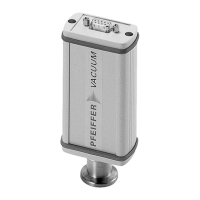
Setting the address
selection switch
Fig. 2: Setting the address selection switch
Remove the rubber plugs (not shown in the illustration) from the address selector
switch, and set the required address according to the relevant connection situation.
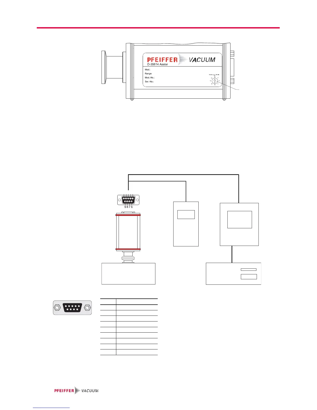
Connecting the trans-
mitter to the DPG 101
controller
Set the address selector switch on the transmitter to RS-232 mode (basic factory-set-
ting).
Connect the transmitter to the control unit using the connection cable.
Switch on the control unit.
Connecting the trans-
mitter to the DPG 109
controller
Up to nine transmitters in series can be conneted to the DPG 109 controller.
Fig. 3: Connections diagram transmitter-DPG
Set address selector switch S on the transmitter to RS-485 mode with the relevant ad-
dress.
Connect the transmitter to the control unit using the connection cable.
Switch on the control unit.