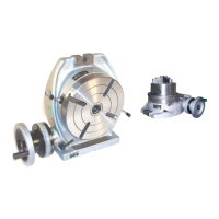
The device described in this manual is a Phase II 221 Series Horizontal & Vertical Rotary Table, designed for precision indexing, circular cutting, angle setting, boring, and spot facing operations. It is a versatile tool suitable for various machining tasks requiring accurate rotational positioning.
Function Description
The rotary table allows for precise angular positioning of workpieces in both horizontal and vertical orientations. Its primary function is to divide a 360° rotation into a specified number of equal divisions, enabling operations like gear cutting, drilling bolt circles, and angular milling. The worm gear mechanism provides fine rotational control, while the dividing plate accessory extends its capability to achieve a wide range of divisions.
Important Technical Specifications
The rotary tables come in various sizes, including 4", 6", 8", 10", 12", and 16" tables, each with specific dimensions detailed in Figure 1 of the manual.
Accuracy (Maximum T.I.P.):
- Flatness of clamping surface: 0.0006"
- Parallelism of clamping surface to base: 0.0008"
- Squareness of clamping surface to angle face: 0.0004"
- Squareness of clamping surface to center slot: 0.0008"
- Concentricity of center bore: 0.0008"
Maximum Spacing Error:
- 6" & 8" tables: 1 minute, 20 seconds
- 10", 12" & 16" tables: 45 seconds
Gear Ratio:
The rotary table has a gear ratio of 1:90, meaning 90 rotations of the handwheel result in one full rotation (360°) of the table. One rotation of the handwheel is equivalent to a 4° rotation of the table.
Micro Collar and Vernier Scale:
The micro collar is graduated in one-minute increments, and a vernier scale (Ref. No. 40) provides angle rotation measurements to an accuracy of ten seconds.
Center Hole:
The table is equipped with a Morse Taper center hole, precision-ground for accurate centering and measuring operations. The specific Morse Taper size varies by table model (e.g., 2MT for 4" and 6" tables, 3MT for 8" and 10" tables, 4MT for 12" and 16" tables).
Dividing Plates Accessory (241-101):
This accessory enables the operator to accurately divide the 360° rotation into divisions from 2 through 66, and all divisibles of 2, 3, and 5 from 67-132. The manual clarifies that the actual divisions available with the standard dividing plate set are "all divisible by 2,3 or 5 from 68-130 and some but not all divisible by 2,3 or 5 from 132-5760 equal divisions," with 67 and 131 not being available.
The dividing plates consist of two plates, each with two faces, offering a total of four different faces with various hole combinations.
- Plate A: 34, 37, 38, 39, and 41 holes
- Plate B: 43, 44, 50, 52, 56, and 61 holes
- Plate C: 46, 47, 49, 51, and 53 holes
- Plate D: 54, 57, 58, 59, 62, and 64 holes
Usage Features
Operation:
- Handwheel Rotation: Always rotate the handwheel (Ref. No. 46) clockwise to eliminate backlash in the worm gear. If over-rotated, turn counterclockwise one full turn, then clockwise to the desired position.
- Worm Shaft Disengagement: The worm shaft (Ref. No. 31) can be disengaged to allow manual rotation of the table. This is achieved by loosening handles (Ref. No. 25 and 39) and turning the vernier collar (Ref. No. 40) clockwise until snug. To re-engage, turn back the vernier collar and secure handle (Ref. No. 25).
- Table Locking: The table is locked by rotating clamp handles (Ref. No. 7) clockwise until snug. Turning them counterclockwise frees the table.
- Angle Indication: A scale and indicator (Ref. No. 22) are provided to verify the angle of rotation. The indicator can be adjusted by loosening its knob (Ref. No. 23).
- Mounting: The table can be mounted horizontally or vertically using the provided slots. It must be securely mounted to the machine work surface. Workpieces and face plates should also be securely clamped.
Dividing Plate Accessory Usage:
The dividing plates are used in conjunction with the handwheel to achieve precise fractional rotations. For example, to achieve 17 divisions, 5 full handwheel rotations and 10 holes on a 34-hole circle are required for each division. The sector arms are used to quickly set the desired number of holes for fractional rotations.
Rotary Table/Lathe Chuck Adapter Plates:
Adapter plates (e.g., 221-354 to 221-366) are available to mount lathe chucks (e.g., 559-110 to 559-116) to the rotary table. The "step" on the adapter plate should face the back side of the lathe chuck. The assembly is then connected to the rotary table's T-slots using T-nuts and bolts.
Worm Gear / Eccentric Sleeve Adjustment:
This procedure ensures proper mesh between the worm gear and the table's top gear. It involves loosening Handle A and Bolt B, then adjusting Limiting Bolt A clockwise to increase mesh or counterclockwise to reduce mesh. The handwheel is rotated to confirm the mesh is within 6°. Locking Bolt B and Handle A are then tightened.
For disengagement, the Indicator is rotated counterclockwise until Bolt C touches the Locating Pin. To engage, rotate the indicator clockwise until Bolt D touches Bolt A.
Maintenance Features
Unpacking and Cleaning:
Upon receipt, check for shipping damage and completeness. The tool is coated with a protective layer that must be removed using mild solvents (e.g., mineral spirits) and a soft cloth. Nonflammable solvents are recommended. Avoid getting cleaning solution on painted components. After cleaning, cover all exposed surfaces with a light coating of oil.
Lubrication:
The rotary table must be kept clean of dirt and chips. Before initial use and before every shift of operation, fill the base cavity with light duty hydraulic fluid or spindle oil through the oil zerts and oil plug (Ref. No. 11). The table should be filled until the oil is just visible in the sight glass. Do not overfill, as the table is not sealed and may leak if overfilled. The oil level should be checked frequently using the sight glass (Ref. No. 8).
Worm Shaft Adjustment:
To compensate for wear in the worm shaft, the lock nut (Ref. No. 35) needs adjustment. Remove the handwheel (Ref. No. 46) and spacer (Ref. No. 36), then tighten the locknut until play is removed from the engaged worm shaft and clamping surface, being careful not to overtighten. Replace the spacer and handwheel.
Eccentric Sleeve Limit Screw Adjustment:
The threaded pin (Ref. No. 29) controls the rotation of the eccentric sleeve. If the worm shaft does not engage the table correctly when the vernier collar is rotated counterclockwise, unscrew the set screw (Ref. No. 28) and adjust the threaded pin until proper engagement is achieved. For model 221-308, the set screw and threaded pin are located in the lower right corner of the base casting (Ref. No. 1).