`
KVM300
2-2
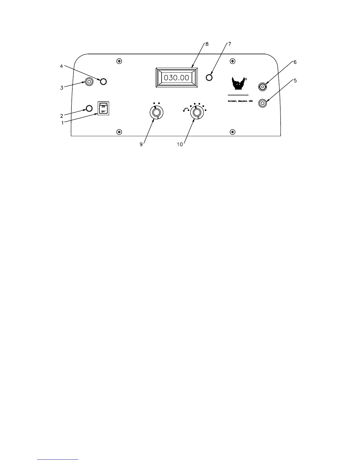
1. CONTROL POWER SWITCH: Depressing this switch will turn on or turn off the control power
of the KVM.
2. LOW BATTERY: Battery needs recharged when lamp is illuminated
3. INPUT JACK: External input / charging jack provides for battery charging or AC operation with
included power adapter.
4. INPUT / CHARGING LAMP: Illuminates when external input / charging power is present.
5. GROUND STUD: This Ground stud must be connected to ground for metering module ground.
6. BNC INPUT CONNECTOR: This BNC input connector connects the meter module to the
divider.
7. BACKLIGHT DIMMER: This dial adjusts the intensity of the backlight for use during low light
conditions.
8. METER: This 4 1/2 digit meter displays the measured value of the input voltage.
9. MEASUREMENT RANGE SELECTOR: This rotary selector changes between the low and
high range of the meter. Meter low range should not be used past 30kV. Meter may not be
accurate past 100% of reading and actual voltage may be much higher than indicated.
10. MEASURING FUNCTION SELECTOR: This rotary selector allows selection of the
measurement function of the KVM.
TECHNOLOGIES
PHENIX