308D
OFFICIAL RADIO SERVICE MANUAL
Supplement No. 5
PHILCO RADIO & TELEVISION CORP.
PHILCO
Service Bulletin-No. 120E
Adjusting Models 80 and 37
0
O
I.F.
I.F.
SENSITIVITY
PRIMARY
SECONDARY
450 K.C.
450 K.C.
LOW
FREQUENCY
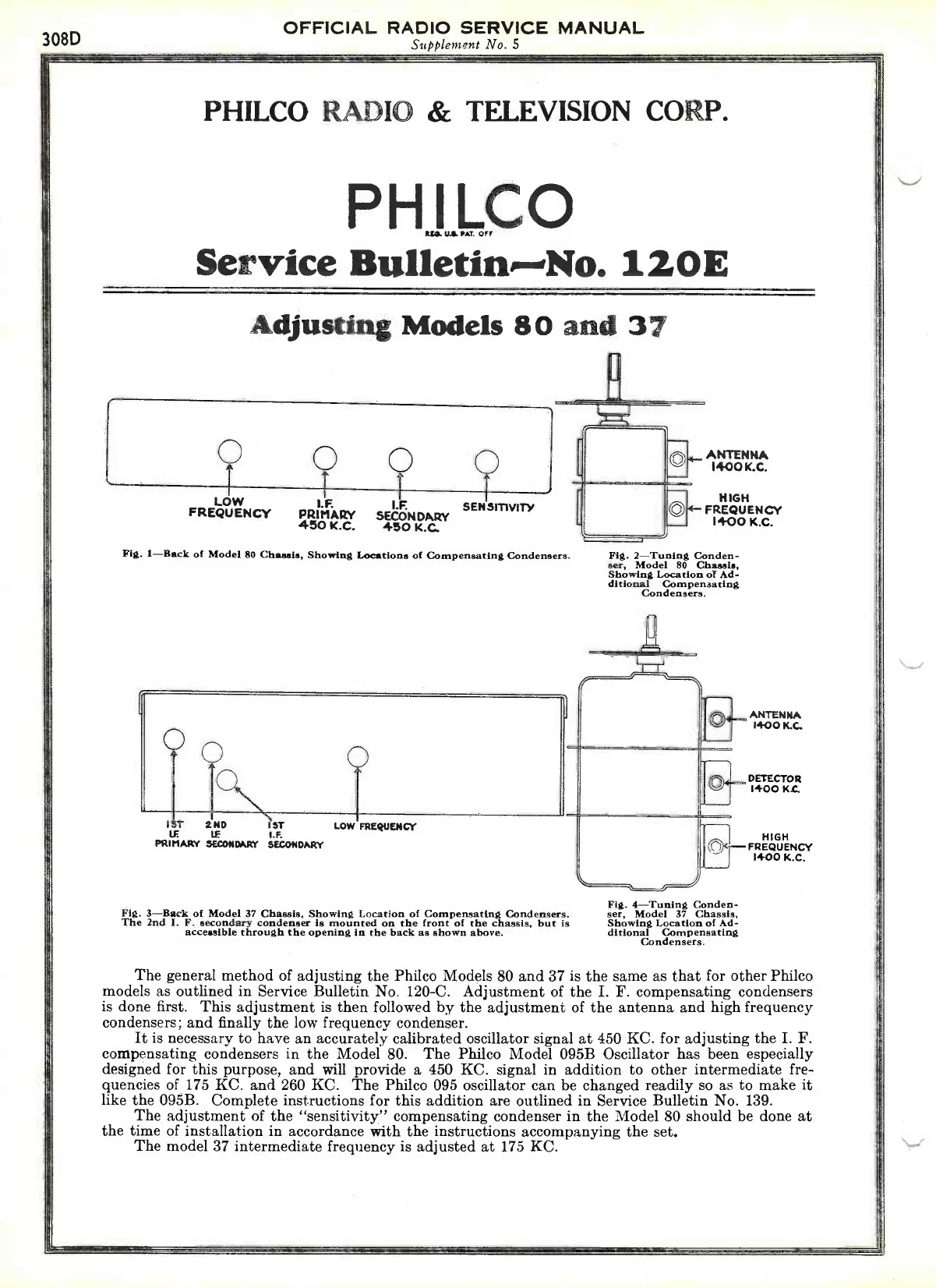
Fig. 1-Back of Model 80 Chassis, Showing Locations of Compensating Condensers.
Q
0
1ST
2ND
1ST
LE 11
I.F.
PRIMARY SECONDARY SECONDARY
LOW FREQUENCY
Fig. 3-Back of Model 37 Chassis, Showing Location of Compensating Condensers.
The 2nd I. F. secondary condenser is mounted on the front of the chassis, but is
accessible through the opening In the back as shown above.
ANTENNA
1400 K.C.
NIGH
FREQUENCY
1400 K.C.
Fig. 2-Tuning Conden-
ser, Model 80 Chassis,
Showing Location of Ad-
ditional
Compensating
Condensers.
Fig. 4-Tuning Conden-
ser, Model 37 Chassis,
Showing Location of Ad-
ditional
Compensating
Condensers.
ANTENNA
1400 K.C.
DETECTOR
1400 K.
HIGH
FREQUENCY
1400 K.C.
The general method of adjusting the Philco Models 80 and 37 is the same as that for other Philco
models as outlined in Service Bulletin No. 120-C. Adjustment of the I. F. compensating condensers
is done first.
This adjustment is then followed by the adjustment of the antenna and high frequency
condensers; and finally the low frequency condenser.
It is necessary to have an accurately calibrated oscillator signal at 450 KC. for adjusting the I. F.
compensating condensers in the Model 80.
The Philco Model 095B Oscillator has been especially
designed for this purpose, and will provide a 450 KC. signal in addition to other intermediate fre-
quencies of 175 KC. and 260 KC. The Philco 095 oscillator can be changed readily so as to make it
like the 095B. Complete instructions for this addition are outlined in Service Bulletin No. 139.
The adjustment of the "sensitivity" compensating condenser in the Model 80 should be done at
the time of installation in accordance with the instructions accompanying the set.
The model 37 intermediate frequency is adjusted at 175 KC.
 Loading...