•
•
• •
•
•
•
•
•
•
•
•
•
?rlodlll 3 7-620
FOR MEMBERS OF
RADIO MANUFACTURERS SERVICE
SERVICE BULLETIN
No. 150
General Description
Model 37-620 is a 6 tube superheterodyne receiver for operation
on altern ating current ,
having three tuning ranges , covering
stand ard broadcast and short-wave frequencies, and using the new
Philco High-Efficiency self-centering glass tubes .
The circuit includes the Philco "Foreign Tuning Syst em"-
controlled by the tuning range switch - which provides maximum
sensitivity and noise reduction, when used with the
Philco High
Efficiency Aerial supplied with the receiver . One stage of Radio
Frequency amplification which greatly increases the signal-to-
noise ratio, automatic bass compensation in the volume control
circuit , and a separate diode circuit for automatic volume con-
trol are also incorporated in this receiver.
The red and black leads of the High -Efficiency Aerial "trans-
mission line " are connected to terminals 1 and 2 respectively, of
the terminal panel provided at the rear of the chassis. Connect
the jumper on the terminal panel across terminals 3 and 4.
If a tempor ary aerial is used , the jumper should be across ter-
minals 2 and
3. The aerial connects to terminal 1 and the ground
to terminal 3.
A good ground connection is desirable in all installations .
Make the ground connection from the nearest water or radiator
pipe to termin al 3 on the terminal panel.
CONSTRUCTION
all coils; and other parts necessary for the associated circuits ,
The unit is separately mounted on rubber grommets, cushioning
it from the main chassis .
(2) The Intermediate Frequency unit, mounted on the right
hand side of the chassis (facing front of set) consists of the Inter -
mediate Frequency transformers, compensating condensers, a
6K7G tube for the
I. F. Amplifier stage, and a 6Q7G tube as the
second detector - automatic volume control and first audio stage.
All voltages supplied to the
I. F . and R. F. units are furnished
from a terminal strip mounted on this unit.
(3) The Power Pack and Audio Output circ uits, together with
the required voltage dividers and filter condensers are mounted
in the power unit. This unit contains a 6F6G tube and a 5Y4G
tube for the Power output and rectifier circuits respectively; and
the combined tone control and power switch. The socket for the
5Y4G tube is mounted on the power transforme r.
Schematic Diagram Fig . 5 is numbered , indicating all im-
portant parts . These numbers correspond with the parts layout
shown in Fig. 6. In addition , the range switch wafers are shown
on the schematic diagram. The contacts on each wafer are lettered
and numbered to indicate their connection points in the schematic
diagram, which are also lettered and numbered. The physical
drawings of each coil used in the receiver are also shown on sche-
matic diagram Fig. 5. The connections of these coils are numbered
on the coil Drawing and on the schematic diagram .
The chassis is constructed in three basic assembly units, con-
centrating each circuit in a single unit .
(1) The Radio Frequen cy unit , located in the center of the
chassis, contains a 6K7G tube which functions as a Radio Fre-
quency Amplifier; a 6A8G tube, for the Det€ctor -Oscillator cir-
cuit ; individual Antenn a, R. F. Amplifier and Oscillator coils for
each tuning range; selector switch ; compensating condensers for
Fig. 1 shows the Voltage measurements taken from the bottom
of the sockets at each contact . In Fig . 2, the correct position of
the dial indicator, for proper adjustment of the compensator
· condenser is shown. Fig. • 3 and 4 are the locations of the
I. F . and
R. F . compensators respectively .
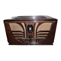
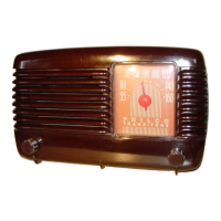
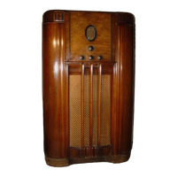
This receiver is used in cabinets type B and
J. These instruc-
tions, however, will cover both types . ·
Electrical Specifications
Voltage Rating : 115 Volts AC.
Frequency Rating: 50 to 60 cycles.
For 25 to 40 cycle operation , the Power Transformer marked
with asterisk in the parts list is used.
Power Consumption : 65 Watts
Types and Number of Tubes: 2 type 6K7G, R. F. and I. F .
Amplifiers ; 1 type 6A8G, Detector-Oscillator; 1 type 6Q7G,
2nd Detector , Automatic Volume Control and 1st Audio ; 1
type 6F6G, Output; and 1 type 5Y4G Rectifier.
Undist orted Output: 3 watts.
Inte rmediate Frequency: 470 K. C.
Tun ing Ranges: Three, Range 1.-530 to 1720 Kilocycles; Range
2.- 2.3 to 7.4 Megacycles ; Range 3. - 7.35 to 22 Megacycles .
Speakers: B Cabinet - S-7.
J Cab inet - HS. -,c=C:.R=E=E=N==;,ca:==:3;:;:,...,-----_
340<~
®
POWER TRANSFORMER DATA
J ••
"U"& N'IJJ.,"'lrut" •
r RE.CTlrlER I
I (i ) I
! ____________________________ l
70'l Z51JV.
bo.OtT. · ln.AUOIO
..J?9.li.._
Fig . I- Socket Voltages
Measured from Socket Contact to Ground
Undersi de of Chassis View
The voltages indicated by arrows were meas ured with a
Philco
025 Circuit Tester wh ich co ntai ns a voltm eter
having a resistan ce of 1000 ohms per volt. Volume Control
at minimum . Rang e Swit ch in broadcas t position . Line
volta ge 115 A. C.
Lead No.
Shown A.C.
Current
on Sche- Volts
matlc
-- --
--- - ---
1-2 120
-
----
---
3- 4
5 .0
2.0 A.
----
- -- - -- -
5- 7 670 70 Ma .
-- --
--- - -- -
6 -
-
-- - - -- -
8- 9 6. 7
2.1 A.
Ru n 2.
Circuit
-- - -
Pri.
F il.
Rectifier
--- - -
High
Volt age
Sec .
Center
T ap of
5- 7
Fil.
Color
---
Whit e
Blue
Yellow
-
Black
Resist-
ance
- - ---
5 oh ms
.1 ohm
145 ohm s
155 ohm s
-----
-
.1 ohm
Speake r Wiring
Wh en replacing an y part of th e
spea ker, th e hum bucking coil
conn ections should be connected
for minimum hum .
Whil e the circuit arrangement remain s the same, the
po~ition of the parts is slightly chang ed in
thi s Run . Ba kelite conden ser
O Pa rt No. 3793-DG is rem oved from front a nd place d in the rear of
th e chassis . Tubul a r cond enser
O Part No. 30-4380 is rep laced wit h a Part No. 8318-SU bak elite
condenser, pla ced in th e position formerly held by 3793-DG .
Copyright 1936, Philco Radio
& Televisi on Corp orati on