PageZ
PHILCO Service Bulletb1
No. ZSO
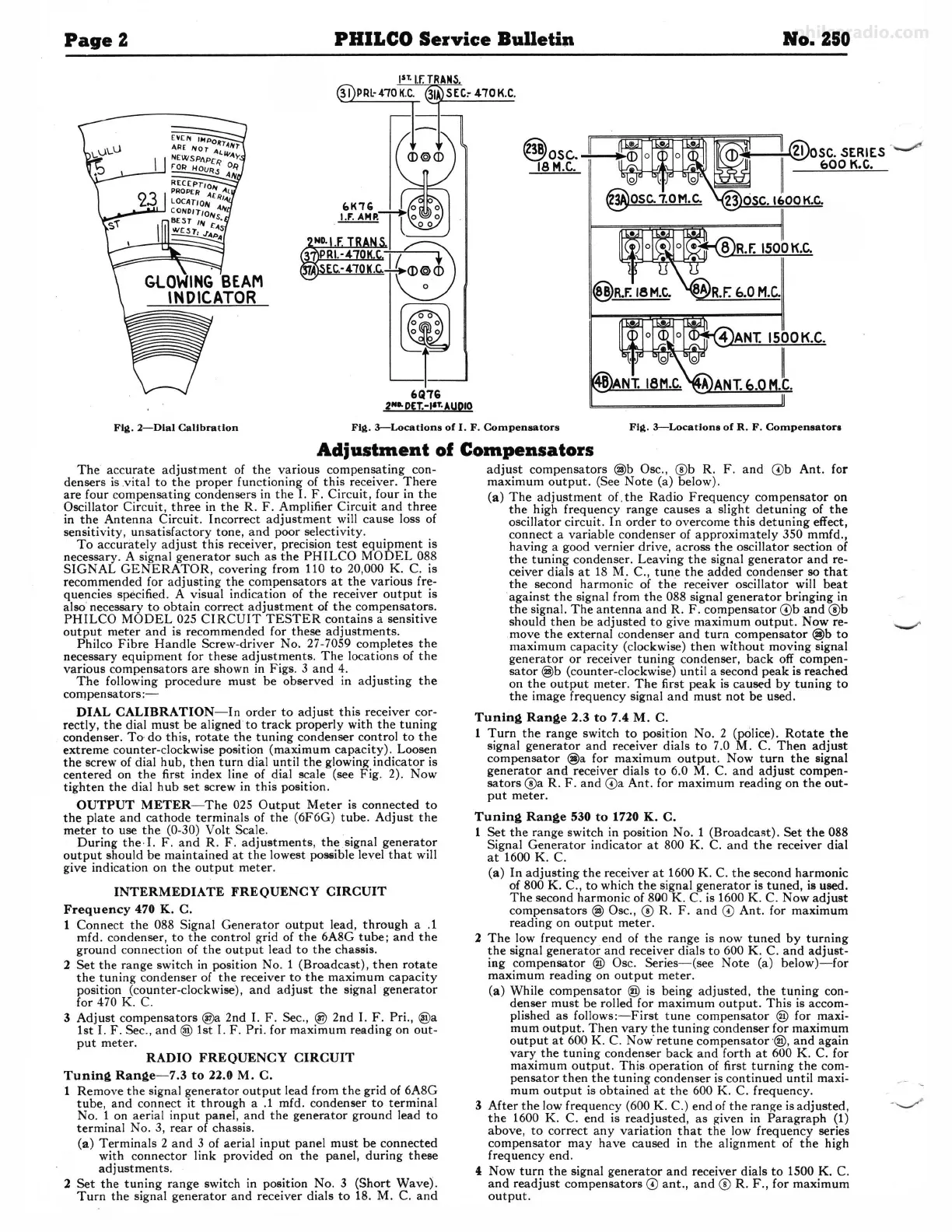
Fljl. 2-Dlal Calibration
FIii,. 3-Locatlons of I. F. Compensators FIii,. 3-Locatlona of R. F.
Compensator
■
Adjustment of Compensators
The accurate adjustment of the various compensating con-
densers is .vital to the proper functioning of this receiver. There
are four compensating condensers in the
I. F. Circuit , four in the
Oscillator Circuit, three in the R. F. Amplifier Circuit and three
in the Antenna Circuit. Incorrect adjustment will cause loss of
sensitivity, unsatisfactory tone, and poor selectivity.
To accurately adjust this receiver, precision test equipment is
necessary. A signal generator such as the PHILCO MODEL 088
SIGNAL GENERATOR, covering from 110 to 20,000
K. C. is
recommended for adjusting the compensators at the various fre-
quencies specified . A visual indication
of the receiver output is
also· necessary to obtain correct adjustment of the compensators .
PHILCO MODEL 025 CIRCUIT TESTER contains a sensitive
output meter and is recommended for these adjustments.
Philco Fibre Handle Screw-driver
No, 27-7059 completes the
necessary equipment for these adjustments . The locations of the
various compensators are shown in Figs. 3 and 4.
The following procedure must be observed in adjusting the
compensators:-
DIAL CALIBRATION - In order to adjust this receiver cor-
rectly, the dial must be aligned to track properly with the tuning
condenser.
To, do this, rotate the tuning condenser control to the
extreme counter-clockwise position (maximum capacity). Loosen
the screw of dial hub, then turn dial until the glowing indicator is
centered on the first index line of dial scale (see Fig. 2). Now
tighten the dial hub set screw in this position.
OUTPUT METER-The 025 Output Meter is connected to
the plate and cathode terminals of the (6F6G) tube. Adjust the
meter to use the (0-30) Volt Scale.
During the ·!. F. and R. F. adjustments , the signal generator
output should be maintained at the lowest
poS&ible level that will
give indication on the output meter.
INTERMEDIATE FREQUENCY CIRCUIT
Frequency 470 K. C.
1 Connect the 088 Signal Generator output lead, through a .1
mfd . condenser, to the control grid of the 6A8G tube; and the
ground connection of the output lead to the chassis.
2 Set the range switch in position No. 1 (Broadcast), then rotate
the tuning condenser of the receiver to the maximum capacity
position (counter-clockwise), and
adjw,t the signal generator
for 470
K. C.
3 Adjust compensators @a 2nd I. F. Sec., @ 2nd I. F. Pri ., @a
1st I. F. Sec., and @ 1st I. F. Pri. for maximum reading on out-
put meter.
RADIO FREQUENCY CIRCUIT
Tuning Range - 7.3 to 22.0 M. C.
1 Remove the signal generator output lead from the grid of 6A8G
tube, and connect it through a .1 mfd. condenser to terminal
No . 1 on aerial input panel, and the generator ground
lea<l to
terminal No . 3, rear of chassis .
(a) Terminals 2 and 3 of aerial input panel must be connected
with connector link provided on the panel, during these
adjustments .
2 Set the tuning range switch in position No. 3 (Short Wave) .
Turn the signal generator and receiver dials to 18. M. C. and
adjust compensators
@b Osc., @b R . F . and © b Ant. for
maximum output. (See Note (a) below).
(a) The adjustment of . the Radio Frequency compensator on
the high frequency range causes a slight detuning of the
oscillator circuit . In order to overcome this detuning effect,
connect a variable condenser of
approxim:itely 350 mmfd.,
having a good vernier drive, across the oscillator section of
the tuning condenser. Leaving the signal generator and re-
ceiver dials at 18 M .
C., tune the added condenser so that
the second harmonic of
the receiver oscillator will beat
against the signal from the 088 signal generator bringing in
the signal. The antenna and R. F . compensator
©b and @b
should then be adjusted to give maximum output. Now re-
move the external condenser and turn compensator
@b to
maximum capacity (clockwise) then without moving signal
generator or receiver tuning condenser, back off compen-
sator
@b (counter-clockwise) until a second peak is reached
on the output meter. The first peak is caused by tuning to
the image frequency signal and must not be used.
Tuning Range 2.3 to 7.4 M. C.
1 Tum the range switch to position No . 2 (police) . Rotate the
signal generator and receiver dials to 7.0
M. C. Then adjust
compensator
@a for maximum output . Now tum the signal
generator and receiver dials to 6.0 M. C. and adjust compen-
sators@a R. F. and
© a Ant. for maximum reading on the out-
put meter.
Tuning Range 530 to 1720 K. C.
1 Set the range switch in position No. 1 (Broadcast). Set the 088
Signal Generator indicator at 800
K. C. and the receiver dial
at 1600
K. C.
(a) In adjusting the receiver at 1600
K. C. the second harmonic
cl 800 K. C., to which the signal generator is tuned , is used.
The second harmonic of
800 K. C. is 1600 K. C. Now adjust
compensators
@ Osc., ® R. F. and © Ant. for maximum
reading on output meter.
2 The low frequency end of the range is now tuned by turning
the signal generator and receiver dials to 600 K.
C. and adjust-
ing compensator
® Osc. Series - (see Note (a) below)-for
maximum reading on output meter .
(a) While compensator @ is being adjusted, the tuning con-
denser must be rolled for maximum output. This is accom-
plished as follows: - First tune compensator
® for maxi-
mum output. Then vary the tuning condenser for maximum
output at 600
K. C. Now· retune compensator ·®, and again
vary the tuning condenser back and forth at 600 K. C. for
maximum output. This operation of first turning the com-
pensator then the tuning condenser is continued until maxi-
mum output is obtained at the 600 K.
C. frequency.
3 After the low frequency (600 K.
C.) end of the range is adjusted,
the 1600
K. C. end is readjusted, as given in Paragraph (1)
above, to correct any variation that the low frequency series
compensator may have caused in the alignment of the high
frequency end .
4 Now tum the si.gnal generator and receiver dials to 1500 K. C.
and readjust compensators © ant ., and ® R. F ., for maximum
output.
 Loading...