PH·ILCO
REG. U.tl. PAT. or,.
Service Bulletin,... No. 201
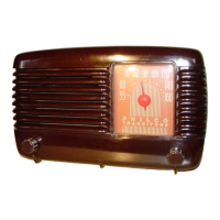
Model 200
Philco Model 200 is a superheterodyne radio
receiver designed especially to deliver high fidel-
ity reproduction of broadcasts. The audio
response of this model extends from 30 to 7 500
cycles. This is made possible partly by the design
of the
R. F. and I. F. circuits, which are so
arranged that by means of a set of variable
resistances in the
I. F. circuits the tuning can
either be broadened to take in the high fidelity
transmissions which cover more than a single
channel, where conditions permit; or sharpened
when necessary and when full high fidelity cannot
be used to advantage. The design of the audio
circuit, speaker and cabinet and the use of a
special "Sound-Diffuser' consisting of a scienti-
fically arranged group of sound-radiating vanes,
also contribute greatly to the high fidelity result.
The Selectivity-Fidelity Control is the most
important adjustment in this receiver. To oper-
ate this control properly requires a thorough
understanding of its functions and its relationship
to the performance of the set. Broad tuning in
the R. F. and
I. F. circuits is required for the
passage of a broadcast signal without any
tendency to lose the higher audio frequencies
contained in the side bands. This condition is
obtained when the selectivity-fidelity control is
Tube Socket Voltages
Det. 1st 2d
Shadow-
Ori-
Out-
Circuit
R.F.
Osc. I.F. I.F.
meter A.F.
ver
put
Rect.
Control
--- - - -- -- -
-
-
Type Tube
78 6A7 78 78
Test
Points
37 75
42
42
5Z3
42
-- ---
-
-
--
-
- -
--
F to F .........
6.3
6.3 6.3 6. 3 6. 3 6.3 6.3 6. 3
5.0
- --- - - --
-
-
-
--
PtoK ...... 225 210
210
220
63 110
225
335
350•
--
--- - - -- - - -
-
SGtoK .......
80
(G3&5-K)
73 76
225
335
73
...
335
...
--- - - -- - - -- -
KtoGnd .....
3
8
8 4 0 0 0
0
0
..
--- - - -- - - -- --
CGtoK ....... 0.2
0 0.2
4 0
0.2
35
...
35
---
-
- -
--
- -
- -
6A7-GltoK ..
22.0
-
6A7-G•to K ..
90.0
turned to the extreme right hand position. In
this position, maximum fidelity and minimum
selectivity will be obtained. This setting will
enable the audio amplifier and speaker to repro-
duce the widest possible range of audio fre-
quencies, but should only be used when no
broadcasting station within the range of the
receiver is operating on a channel within ten
kilocycles of the station being received. As the
control is turned toward the left, the selectivity
is gradually increased with an attendant gradual
decrease in response to the higher frequencies.
With this control in the left hand position, the
tuning will be extremely sharp.
Model 200 uses the following tubes: Type 78
R. F., type 6A7 detector-oscillator, two type 78
I. F., type 37 Shadowmeter control tube, type
7 5 2d detector-1st audio, type 42 driver, two
type 42 output tubes used as triodes and a type
5Z3 rectifier. The interm ediate frequency
(I. F.)
is 175 kilocycles and the power consumption is
130 watts. The Model 200
will receive broad-
casts from 540 to 1720 kilocycles, which includes
all standard broadcasts and some of the police
broadcast frequencie s. This model is for use on
alternating current (A. C.) only.
Power Transformer Data
Terminals A.C. Volts
Circuit Color of Leads
1-2 120 Primary
White
3-5
780
Plates of
5Z3
Yellow
6-7
5.0
Filament of 5Z3
Blue
8- 10
6.3
Filaments
Black
4
...
Center Tap of 3-5
Y e!low-Green Tracer
9 ...
Center Tap;'of 8-10
Black-Yellow Tracer
Use Fig. 1 when testing voltages as per table above.
The above voltages were obtained using a
high resistance D. C. voltmeter for plate, grid and cathode tests, and an A. C. voltmeter for filaments. Line voltage 115
dial
at 55, volume control at maximum, fidelity control at middle position. •p to ground.
Philco Model 025 Circuit Tester is recommended for making these tests.
TYPE 37 TYPE 15
SHADOW METER CONTROL Z"'DE1, jSTA.F.
Fig. 1-Tube Sockets (Viewed from Underneath)