PHILCO
REO. U.S. PAT. or,
Service Bulletin,.... No. 195
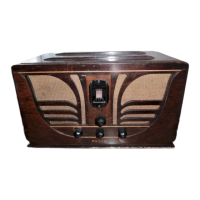
Model 29
Philco Model 29 is a super heterodyne receiver operating on alternating current and capable of receiv-
ing either standard and police broadcasts between 540 and 1720 kilocycles,orshort-wav e stations betwee n
4.2 and 13 megacycl es. The left hand side of the dial is calibr ated in kilocycl es and the right in
megacycles. A two-position switch changes recep tion from standard to short -waves. This model is
equipped with shadow tuning, three point tone control with fixed bass compensation, and automatic
volume contro l. The output is 5 watts.
Model 29 uses a typ e 6-A-7 detecto~-oscillator, two type 39-44 I. F. tub es, type 75 2d detector,
type 42 outp ut tube, and type 80 rectifier. Th e power consumption is 70 watts. The intermediate
frequency is 460 K.C .
Adjusting Compensating Condensers
For adjustment of compensating (padding) condensers in
Model 29, an accurately calibrat ed signal generator and a
special insulated padding wrench and screwdriver are needed.
We suggest the Philco Model 024 Signal Generator or the 048
Tester which includes a similar instr ument . Philco No. 3164
wrench and 27-1159 screwdriver are recommended in addition.
Adjustments are made in the following order:-
ADJUSTMENT OF INTERMED[ATE FREQUENCY-
Remove the grid clip from the type 6-A-7 tube and connect
the "ANT" output terminal on the signal generato r to the
grid cap of the tube. Connect the "GND" termina l of the
signal generator to the "GND" terminal of the receiver chassis.
Connect the output meter to the primary terminals of the
output transformer. Set the signal generator at 460 K.C. (the
interm ediate frequen cy of Model 29) turn wave-band switch
of receiver to left and dial to 600 K.C. Turn receiver and
Signal Generator "ON". Adjust each of the I. F. compen-
sating condensers in turn, to give maximum response in the
output of the receiver. The three pairs of
I. F. compensating
condensers are located, one pair at the top of each of the three
I. F. transforn ,er shields. These are the meta l "Cans" near
the rear of chassis. Each of these transfo rmers has a dual
compensating condenser mounted at its top, and accessible
thru a hole in the top of the coil shield. In the dual compen-
Tube Socket Volta~es -(Line Voltage 115)
Del. 1st
2nd 2nd
Out-
Rectl-
Function Osc.
I. F. I. F. Det. put
fler
-- -- -- --
--
Type 6A7
39/ 44 39/44
75 42 80
--
-- -- --
--
Filament (F to F) ...
..
6.3 6.3 6.3 6.3 6.3 5.0
-- -- -- -- -- -
Plate (P to K) .. 210 200 200 200
300
310
-- --
--
--
--
- -
Screen (SG to K) . ....
80 80 80
315
--
--
-- -- -- --
Cathode (K to GND ) ..
4.8 4.8
4.8
0 0 ...
-- -- --
--
--
6-A-7 Grid GI to K .. 35 ...
...
.. ...
-- --
--
--
--
0-A-7 Grid 02 to K .. 170 ... ... ... . ..
sators, the Primary circuit is adjusted by turning the screw;
the secondary circuit is adjusted by turning the hex-head nut .
ADJUSTMENT OF WA VE TRAP-Replace the grid clip
upon the Detector-Oscillator tube (Type 6-A-7). Connect the
output leads from the Signal Generator directly to the antenna
and ground terminals of the receiver. Set the wave-band
switch of the receiver to the standard broadcast band (left
hand position ) and the Stat ion Selector at the low frequency
(540 K.C.) end. Adjust the Wave Trap condenser to give
MINIMUM response to a 460 K.C . Signal from signal gen-
erator. The Wave Trap CD is located at rear and underneath
the chassis, and is shown in Figure 4. It is reached from the
rear of the chassis, thru hole at right hand end of set base.
DETECTOR; AND OSCILL ATOR- "HIGH" AND
"LOW FREQUENCY" ADJUSTMENTS - The "Antenna"
and "Oscillator H. F." compensa tors are
located on top of the
tuning condenser assembly, reached from above.
Set the signal gener'ator at 1500 K.C ., tune in this signal on
the set, and adjust the antenna compensator 0 (nearest
tuning cont rol), to give maxim um reading in the output meter .
Next adjust the oscillator H. F. condenser
@, located on
the other section of tuning condenser, to maximum reading .
Finally set the signal generator at 600, tune in th is signal and
adjust the oscillator L. F. condenser, locate d underneath
chassis (@ in Fig. 4) to maximum reading. This adjustment
is reached thru the hole in top of chassis, between the two elec-
trolytic condensers (left-han d end of chassis when facing rear).
Power Transformer Voltages
Terminals A. C. Volts
Circuit Color of
Leads
1-2 120
Primary
Whit,o
3--4
5.0 Fil. of 80
Blue
5--7
746
Plates of 80 Yellow
8-10 6.3
Filaments
Black
6
Center of 5--7
Black- Yellow Trac er
9
. ..
Cente r of 8-10
Yellow- Green Tracer
Th e above tests were made with an A. C. voltmeter for filament voltage, and a high-resistance D. C. voltmet er for all others. Dial at 550 K.C. , wave-band , witch
to left, volume control at maximum . Tests made with test prods applied to sockets underneath
chassis.
80
RECTIFIER
~
Fig. 1- Tube Socket Layout
39-44
1'
1
IF.
Fig. 2-Top View
-----t--42
80
,,._;:::::;;:::=;;::=;t-75