PHILCO
I ... U.S.PAT. OfF.
Service Bulletin No. 2.20
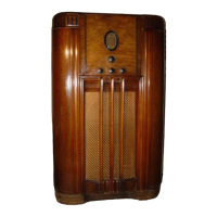
Model 650
Type Circuit: Superheterodyne, with preselector R.F.
amplifier, and push-pull pentode output (10 watts); built in
connections for Philco All-wave aerial; aerial selector built
into and operated by wave-band switch.
Power Supply: Alternating Current. Voltage and fre-
quency as specified on chassis nameplate.
Tubes Used: 1 type 78, R.F.; 1 type 6A7, Detector-
Oscillator; 1 type 78, l.F.; 1 type 75, 2d Detector and 1st A.F.;
1 type 42 Driver; 2 type 42 Push-Pull Output; 1 type
EO
Rectifier.
Wave Bands: Four: (l)Long-wave (U.S. Weather Forecasts);
(2) Standard (with some Police); (3) Police; (4) Short-wave.
Coverage of Each Band: Band 1, 145 to 390 K.C.; Band 2,
540-1720 K.C.; Band 3, 2.2 to 2.6 M.C.; Band 4, 5800-18000
K.C. (5.8 to 18.0 megacycles).
· Tuning Drive: Dual planetary, ball bearing. 80 to 1
ratio for slow-speed tuning.
Tone Control: 4-position, with bass compensation effective
in first position (counter-clockwise).
Intermediate Frequency: 460 K.C.
Power Consumption:
98 watts.
Speaker: 650B (Code 121); K-17, 650X, 650MX, 650-H,
(Code 122); H-13.
Tube Socket Voltages (Line Voltage 115)
Measured to Ground
78
6A7
78
75
42
42
Tube
R.F.
Det.
I.F.
2d
Driver
Out-·
Osc. Det ..
put
Point
p
55
200 200 115 200 300
---
SG 90 90
90
. ''
200
300
---
---
K 2.2 2.3
2.6
. . . ...
. . '
6A7:Gu,=155
Above voltages were obtained by using a PHILCO type 025
Circuit Tester (or 048A All-purpose Tester), using test prods
applied to underside of chassis. Volume control at minimum;
dial at 55; waveband switch counter-clockwise (band 1). Use
Fig. 1 for test points. Type K-17 speaker employed.
ITT
er
80
RECTIFIER.
78
I.F.
Fig. 1. Tube Sockets as viewed from bottom.
Power Transformer Data
Term-
A.C.
Current
Circuit Color
inals
Volts
---
1-2
120
......
Primary
White
---
3-5
760
140 M.A.
Secondary
Yellow
---
6--7 5.0
2.0 A.
Fil. Rect.
Blue
---
8-9 6.3
3.75 A.
Filaments
Black
4
.. .
......
Center Tap of
Yellow,
Green
3-5
Tracer
Adjusting Compensating Condensers
Fig. 2. Locations of Compensating Condensers
Adjustment of compensating condensers in Model 650
requires an accurate signal generator covering long-wave,
standard wave, police, and short-wave frequencies. The
PHILCO Model 088 All-Wave Signal Generator, having a
continuous range of from 100 to 20000 K.C., is ideal for this
purpose.
An output meter is also needed. PHILCO Model 025
Circuit Tester includes a high grade output meter.
Philco No. 3164 fibre wrench and No. 27-7059 fibre-handled
screwdriver complete the equipment needed for making these
adjustments. The locations of the various compensating
condensers is shown in Fig. 2. Connect the output meter to
the plate contacts of the 42 output tubes (using the adapters
provided with the "025") and set it at the 0-30 volt range.
I.F.-Set the Signal Generator at 460 K.C., and attach its
antenna lead to the grid cap of the 6A7 tube on the Model 650
(having removed the grid clip from the tube). Connect the
ground terminal of the Signal Generator to the ground term-
inal of the set. Turn on the set, turn the waveband switch to
second position (standard) and set dial at 55. Now with the
fibre screwdriver, adjust condensers
@ and @ (2d I.F.)
and then
@) and @) (1st I.F.) until maximum reading is
obtained in the output meter. Turn down the "attenuator"
on the signal generator if the output meter needle goes off the
scale.